AO high-efficiency nitrogen and phosphorus removal system

A high-efficiency technology for denitrification and phosphorus removal, applied in water/sewage multi-stage treatment, chemical instruments and methods, water/sludge/sewage treatment, etc. The problems of low concentration and unfavorable denitrification efficiency can achieve the effect of strong shock load resistance, stable operation and low operating cost.

Active Publication Date: 2011-07-20
TIANJIN MUNICIPAL ENG DESIGN & RES INST
View PDF5 Cites 8 Cited by
  • Summary
  • Abstract
  • Description
  • Claims
  • Application Information

AI Technical Summary

Problems solved by technology

Discharge standards have gradually stricter requirements for effluent nitrogen, that is, higher and higher requirements have been put forward for the process of nitrification and denitrification. To achieve a good denitrification effect in the traditional denitrification process, one must ensure sufficient nitrification time. Guarantee the growth of a large number of nitrifying bacteria to achieve the purpose of nitrification, while the traditional nitrogen and phosphorus removal process has a low sludge concentration in the aeration tank, a long time for nitrification, a large tank capacity, high civil construction costs, and a large area; Second, it is necessary to ensure the reflux of the mixed liquid in the aeration tank, and return the nitrate nitrogen generated in the aerobic zone to the anoxic zone, so that denitrification can proceed smoothly, but increasing the internal reflux ratio alone will significantly affect the anoxic environment of the anoxic tank , which is very detrimental to the improvement of denitrification efficiency

Method used


Image

  • AO high-efficiency nitrogen and phosphorus removal system
  • AO high-efficiency nitrogen and phosphorus removal system

Examples


Embodiment Construction

[0025] The detailed description of the AO high-efficiency denitrification and dephosphorization system of the present invention will be described below in conjunction with the embodiments and the accompanying drawings.

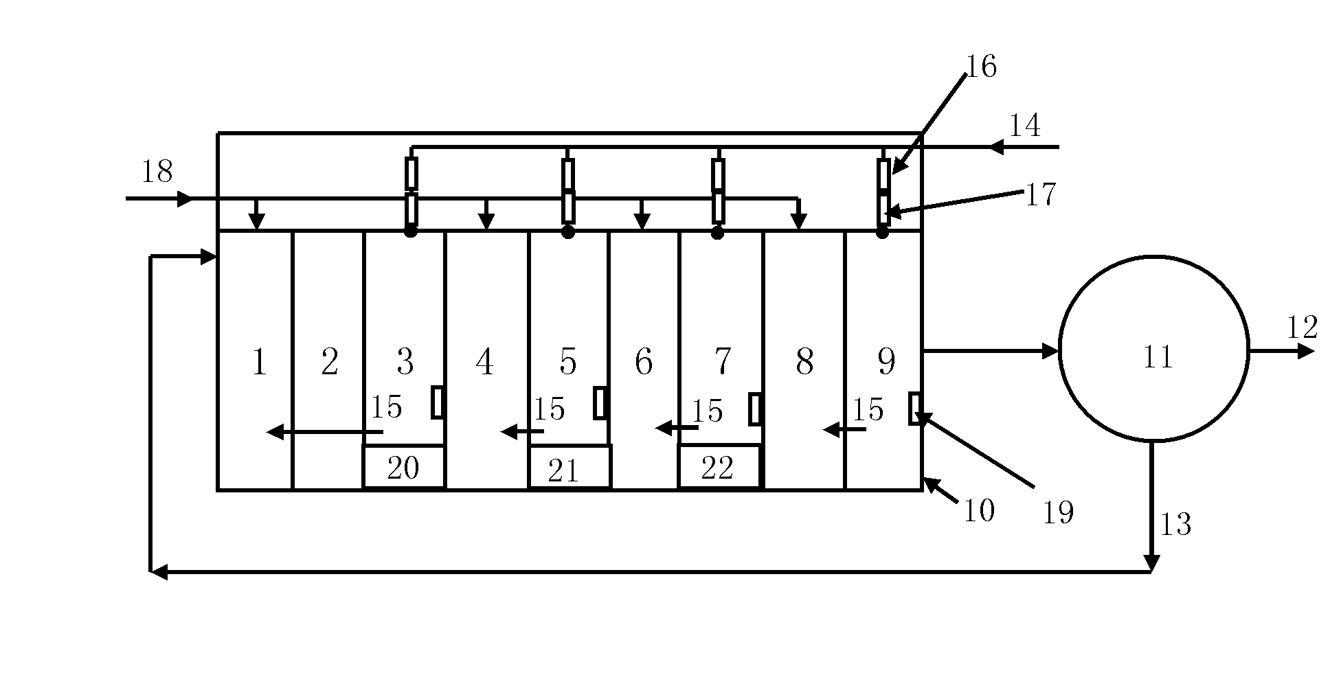
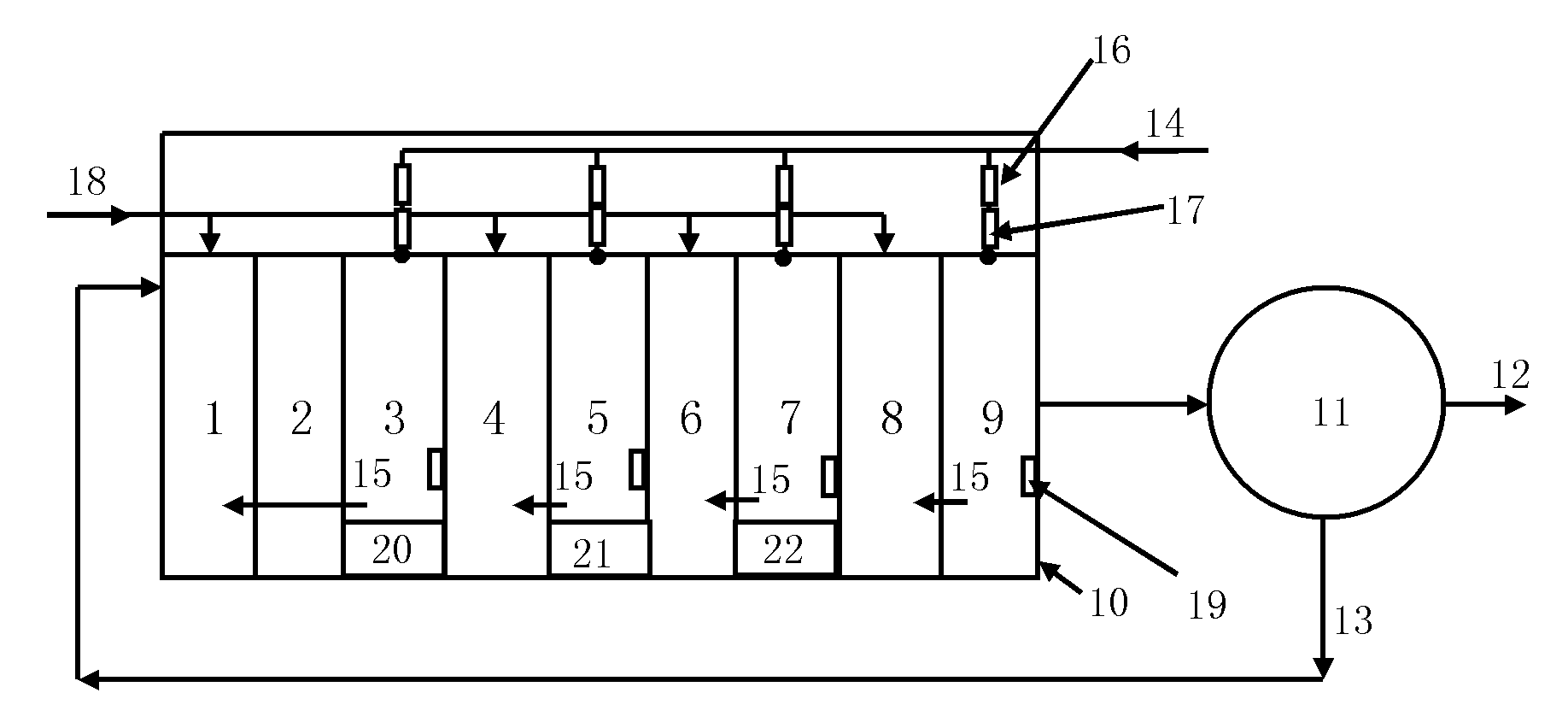
[0026] Such as figure 1 As shown, the AO high-efficiency nitrogen and phosphorus removal system of the present invention includes a biological pool 10 and a secondary sedimentation tank 11 connected to the sewage outflow end of the biological pool 10. The sewage enters the biological pool 10 in different proportions, and then undergoes secondary sedimentation. Pool 11 flows out. The biological pool 10 is sequentially provided with a first-level anoxic zone 1, an anaerobic zone 2, a first-level aerobic zone 3, a first-level motorized zone 20, a second-level anoxic zone 4, and a second-level good zone from sewage inflow to sewage outflow. Oxygen zone 5, secondary maneuvering zone 21, tertiary anoxic zone 6, tertiary aerobic zone 7, tertiary maneuvering zone 22,...


PUM


Abstract

The invention discloses an anaerobic-oxic (AO) high-efficiency nitrogen and phosphorus removal system. The AO high-efficiency nitrogen and phosphorus removal system is provided with a secondary sedimentation tank which is communicated with a sewage outflow end of a biological tank, wherein a first-level anoxic zone, an anaerobic zone, a first-level oxic zone, a second-level anoxic zone, a second-level oxic zone, a third-level anoxic zone, a third-level oxic zone, a fourth-level anoxic zone and a fourth-level oxic zone are arranged in the biological tank from sewage inflow to sewage outflow inturn; the secondary sedimentation tank comprises a sewage outflow port and a sludge reflux pipe; the sludge reflux pipe is communicated with the first-level anoxic zone in the biological tank, and isused for injecting reflux sludge into the first-level anoxic zone; sewage is injected from the upper sides of the first-level anoxic zone, the second-level anoxic zone, the third-level anoxic zone and the fourth-level anoxic zone from a sewage inflow port through pipelines respectively; stirrers which ensure that sediments are not generated in mixed liquid are arranged in the anoxic zones and theanaerobic zone from the first level to the fourth level; and the amount of the sewage which is injected into the first-level anoxic zone, the second-level anoxic zone, the third-level anoxic zone andthe fourth-level anoxic zone is 0 to 40 percent of inflow rate. By the AO high-efficiency nitrogen and phosphorus removal system, the concentration of the sludge in the subsequent levels is improved,the volume of the biological tank is reduced, and engineering investment is saved.

Description

technical field [0001] The invention relates to an AO nitrogen and phosphorus removal system. In particular, it involves a method of making sewage enter the biological pool in different proportions, forming a series of multiple AO pools in the biological pool, and using the available carbon source in the sewage to provide as much nutrition as possible for phosphorus accumulating bacteria and denitrifying bacteria. , Accelerate its growth, thereby significantly improving the efficiency of nitrogen and phosphorus removal AO efficient nitrogen and phosphorus removal system. Background technique [0002] The discharge of organic matter, nitrogen, phosphorus and other nutrients in urban sewage into the water body will cause water pollution and eutrophication. The first-level A standard puts forward stricter requirements on the discharge standards of nitrogen and phosphorus. [0003] The key to achieve the stable standard of Grade A A is the stable standard of total nitrogen. B...

Claims


Application Information

Patent Timeline
Patent Type & Authority Applications(China)
IPC IPC(8): C02F9/14C02F3/30
Inventor 郭淑琴王舜和魏新庆王秀朵张建华王洪云潘留明张莹张泳邓胜琳
Owner TIANJIN MUNICIPAL ENG DESIGN & RES INST
Why Eureka
Try Eureka