Method for testing conductivity of medium material

A technology for dielectric material, charge and discharge testing, applied in the field of testing, can solve the problems of different research purposes, different numbers of electrodes, regardless of storage time and quantity, etc.

Active Publication Date: 2011-07-20
NO 510 INST THE FIFTH RES INST OFCHINA AEROSPAE SCI & TECH
View PDF4 Cites 23 Cited by
  • Summary
  • Abstract
  • Description
  • Claims
  • Application Information

AI Technical Summary

Problems solved by technology

[0004] The conventional conductivity measurement method is not completely suitable for the space charged environment. The main reasons why the conventional method is not suitable for the space condition are as follows: (1) The charge injection method is different, and the charged charge density curve and electric field formed are also essentially different: conventional The voltage of the three-electrode method is provided by a power supply, and the charged surface potential of the medium is formed by charge injection; (2) the number of electrodes is different: the conventional three-electrode method has electrodes on both sides of the medium, and only one side of the medium is charged. The other side is the charge injection surface; (3) The purpose of the research is different: the conductivity measurement of the conventional three-electrode method is related to the loss of power in the medium, regardless of the storage time and quantity after charge injection; (4) leakage The current measurement time is different: the measurement time or reading time of the conventional three-electrode method is several minutes, while the charging or decay cycle of the space medium can be as long as several months, and the change of the medium conductivity will not appear until a long time

Method used


Image

  • Method for testing conductivity of medium material
  • Method for testing conductivity of medium material
  • Method for testing conductivity of medium material

Examples


Embodiment Construction

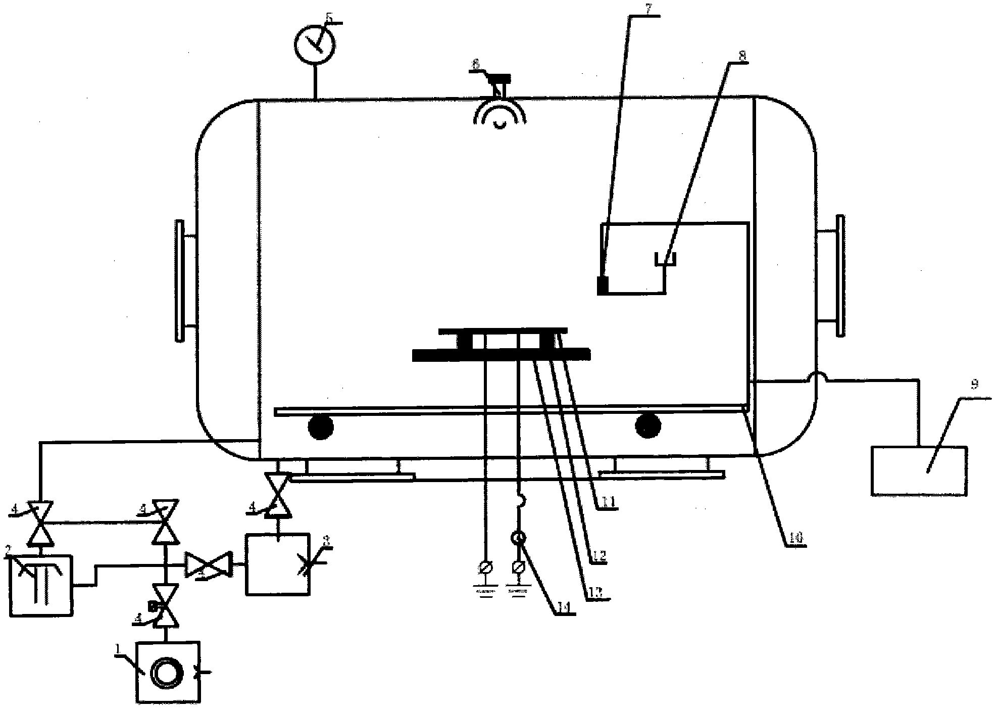
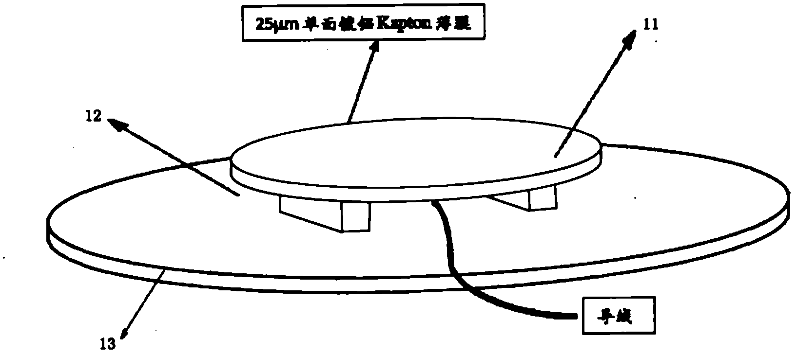
[0025] The testing equipment in the present invention includes a vacuum system, a charging and discharging system, and a potential testing system. The vacuum system includes a vacuum tank, a mechanical pump 3, a diffusion pump 2, a multistage rotary vane pump 1, valves, sealed pipelines and a workbench; the charging and discharging system consists of an electron gun 6 and a sample 11 installation system; the potential testing system includes a potentiometer 9 and microcurrent meter 14, vacuum valve 4 and vacuum gauge 5 are placed in the vacuum tank.

[0026] The connection relationship of this system is: the vacuum tank is placed on the workbench, connected to the mechanical pump through one sealed pipeline through the baffle valve A15, connected to the diffusion pump 2 through the other sealed pipeline through the baffle valve B16, and mechanical pump 3 , multi-stage rotary vane pump 1, and diffusion pump 2 form the pumping unit in the vacuum system; the electron gun 6 is loc...


PUM


Abstract

The invention discloses a method for testing conductivity of medium material, wherein the method comprises the following steps of: positioning an electric potential probe at a zero electric potential position above a sample after the preparation before testing is finished; confirming the placing position of the sample, confirming the position coordinate of an electric potential measuring point bya probe driving mechanism, then closing a vacuum jar, turning on the power of an electric gun, and performing electronic irradiation to the sample via a Faraday cut test; quickly descending an electric potential meter probe to the front surface of the sample every 10 minutes to perform inducted non-contact measurement, wherein the data measured by a micro galvanometer and the electric potential probe is waved between negative 0.5% and positive 0.5%, then the charge of the sample is regarded as saturation; turning off the electric gun, attenuating the similar process via a tapping index form in the sample interior electric charge Q and measuring the electric potential decay process of the sample; in a word, the attenuation relationship of the surface electric potential of the sample along time is measured by a surface electric potential probe, and the conductivity of the sample can be calculated according to the sample surface attenuated electric potential at different time. The conductivity testing equipment in the invention can be applied to hazard assessment of deep charging, and also can provide valuable engineering data for the protection of deep charging or discharging.

Description

technical field [0001] The invention relates to a charging and discharging test method for a dielectric material, in particular to a test system for the surface potential of a dielectric material in a vacuum environment, belonging to the testing field. Background technique [0002] In order to reduce the launch weight and meet the electrical, thermal and mechanical performance requirements of the spacecraft, a large amount of organic dielectric materials are used in the spacecraft. In the space radiation environment, high-energy particles and plasma are easy to deposit inside the dielectric material on the periphery of the spacecraft or on the dielectric material inside the spacecraft through the shielding layer. When the potential difference between the surface of these dielectric materials and other surrounding components or the electric field generated by the deposited charge exceeds a certain threshold, high-energy discharge will directly cause the breakdown of sensitive...

Claims


Application Information

Patent Timeline
Patent Type & Authority Applications(China)
IPC IPC(8): G01R27/02
Inventor 李存惠柳青史亮秦晓刚马亚莉
Owner NO 510 INST THE FIFTH RES INST OFCHINA AEROSPAE SCI & TECH
Why Eureka
Try Eureka