Optical fiber laser and collimator thereof

A fiber laser and collimator technology, which is applied in the field of optical collimators, can solve the problems of high cost and large reduction in beam quality, and achieve the effects of low cost, reduced processing cost, and elimination of system aberrations

Inactive Publication Date: 2011-07-27
INST OF IND TECH GUANGZHOU & CHINESE ACADEMY OF SCI
View PDF12 Cites 16 Cited by
  • Summary
  • Abstract
  • Description
  • Claims
  • Application Information

AI Technical Summary

Problems solved by technology

Existing collimators generally use technologies such as C-LENS (single-element spherical lens) or G-LENS (gradient index lens). C-LENS is a single-element spherical lens. The beam quality of the output light after the collimator is greatly reduced; while G-LENS is a gradient index lens, and its cost is relatively high

Method used


Image

  • Optical fiber laser and collimator thereof
  • Optical fiber laser and collimator thereof
  • Optical fiber laser and collimator thereof

Examples


Embodiment 1

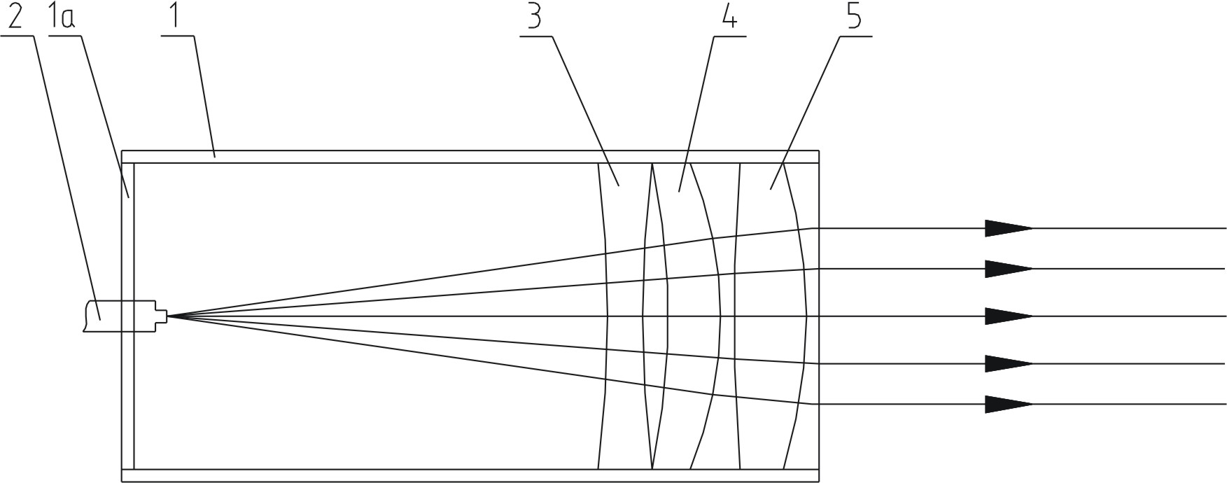
[0029] The structure diagram of one of the embodiments of the collimator of the present invention is as figure 1 As shown, the collimator consists of a lens barrel 1 , an output pigtail 2 fixed at the front end of the lens barrel 1 , and a biconcave lens 3 , a meniscus lens 4 and a biconvex lens 5 fixed in the lens barrel 1 . The front end of the lens barrel 1 is closed by a support plate 1a, and the rear end of the output pigtail 2 extends into the lens barrel 1 from the middle of the support plate 1a. Biconcave lens 3, meniscus lens 4 and biconvex lens 5 are sequentially fixed in lens barrel 1 along the optical path, output pigtail 2 and three lenses 3, 4, 5 form a coaxial optical system, and the rear end surface of output pigtail 2 is located at The focal positions of groups 3, 4, and 5 of the three-piece lens. For ease of description, the surface of each lens that is closer to the output pigtail 2 along the optical path is defined as the front surface. Similarly, the surf...

Embodiment 2

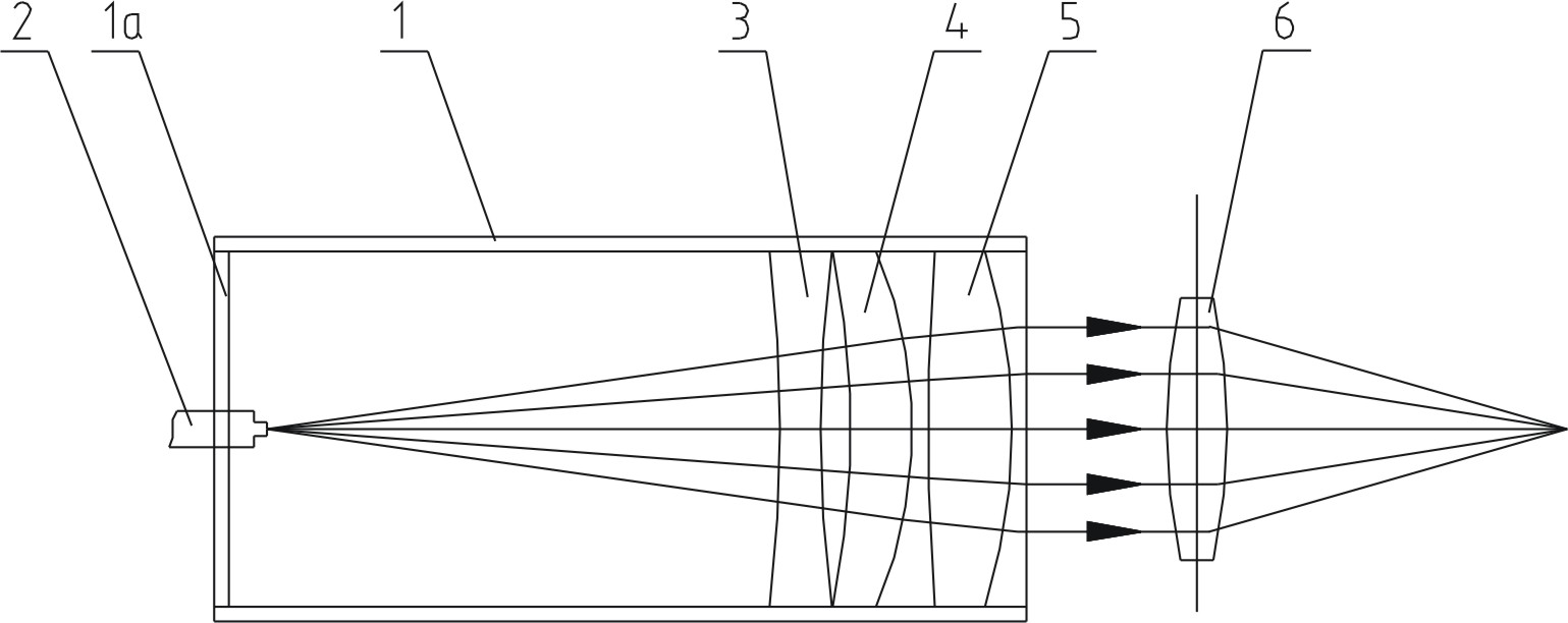
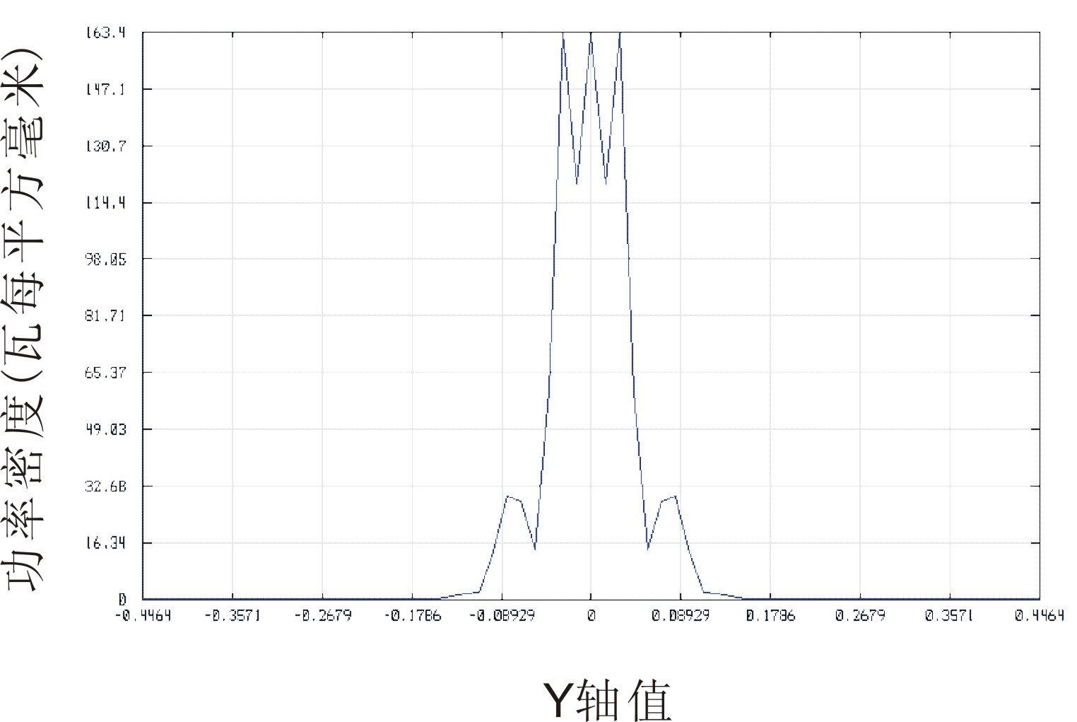
[0033] The structure diagram of one embodiment of the fiber laser of the present invention is as follows figure 2 As shown, the fiber laser comprises the collimator described in Embodiment 1 and a biconvex lens 6 with spherical aberration arranged behind the optical path of the collimator, the biconvex lens 6 with spherical aberration and the three lenses 3 of the collimator, 4, 5 groups with the same optical axis. The biconvex lens 6 with spherical aberration has a front and back curvature radius of 25 mm, a middle thickness of 2 mm, and is made of fused silica. The light beam output by the collimator passes through the biconvex lens 6 with spherical aberration and is focused at a place 26.67 mm away from the rear surface of the lens. image 3 It is the power density distribution diagram at 26.67mm from the rear surface of the lens. It can be seen that the power density is approximately uniform. Figure 4 It is the light distribution diagram at 26.67mm from the rear surfac...

Embodiment 3

[0035] Such as Figure 7 As shown, the difference from Embodiment 2 is that the output pigtail 2 of the fiber laser in this embodiment is formed by fusing and connecting the single-mode optical fiber 21 at the front and the multi-mode optical fiber at the rear. The single-mode optical fiber 21 has a core diameter of 5um and a numerical aperture of 0.14. The core diameter of the multimode fiber is 50um and the numerical aperture is 0.22. After the single-mode laser coming from the single-mode fiber 21 enters the multi-mode fiber through the fusion point, multiple modes are excited, the power distribution tends to be uniform, and the homogenized beam is output through the collimator. The single-mode optical fiber 21 and the multi-mode optical fiber are connected by fusion, so there is little light loss.


PUM


Abstract

The invention discloses a collimator of an optical fiber laser, comprising a lens cone, an output tail fiber and an optical lens, wherein the output tail fiber is fixed on the front end of the lens cone; the optical lens is fixed in the lens cone; the rear end surface of the output tail fiber is positioned on a focal point of the optical lens; and the optical lens comprises a biconcave lens and abiconvex lens which are sequentially arranged along a light path and positioned on a same optical axis. The optical lens of the collimator is mainly a double-lens group comprising the biconcave lens with positive spherical aberration and the biconvex lens with negative spherical aberration, the double-lens group can eliminate system aberration, thereby ensuring that the quality of collimated and expanded output light beams is basically not reduced and keeping the advantage of high light beam quality of the optical fiber laser; and the double-lens group has simple manufacturing process and lowcost, therefore the processing cost of the collimator is reduced. In addition, the invention also discloses the optical fiber laser with the collimator.

Description

technical field [0001] The invention relates to an optical collimator, especially a collimator of a fiber laser, and a fiber laser with the collimator. Background technique [0002] Fiber laser is a revolutionary technology in the laser field. It has the advantages of high output power, high brightness, high beam quality (beam quality close to the diffraction limit), high photoelectric conversion efficiency, high reliability, and long life. A new technology that replaces many existing laser technologies. Since the beam waist diameter of the beam directly output by the output pigtail of the fiber laser is equivalent to the fiber core diameter, which is on the order of several microns to tens of microns, the beam divergence angle is large. Therefore, a collimator is generally connected to the rear end of the output pigtail of the fiber laser, and the light output from the pigtail is collimated and expanded before output. In order to maintain the original technical advantages...

Claims


Application Information

Patent Timeline
Patent Type & Authority Applications(China)
IPC IPC(8): G02B27/30G02B27/00G02B7/02H01S3/067
Inventor 杜卫冲骆健忠
Owner INST OF IND TECH GUANGZHOU & CHINESE ACADEMY OF SCI
Why Eureka
Try Eureka