Flux-cored welding wire integrated forming unit, production method of flux-cored welding wire

A molding unit and flux-cored wire technology, applied in welding media, welding equipment, metal rolling racks, etc., can solve problems affecting filling rate and surface roughness stability, unstable motor speed, disappearing, etc., to eliminate Unstable influencing factors, improving product quality, and improving the effect of stability

Inactive Publication Date: 2016-01-27
TIANJIN SAINTEAGLE WELDING CO LTD
View PDF21 Cites 2 Cited by
  • Summary
  • Abstract
  • Description
  • Claims
  • Application Information

AI Technical Summary

Problems solved by technology

[0005] CN93115833.8 introduces a process of manufacturing flux-cored welding wire by using round steel wire, which mainly includes steps such as rolling out U-shaped grooves on the round steel wire, adding powder, closing, and reducing the diameter. Its main feature is that it does not need to The intermediate annealing link can greatly reduce production costs, but in fact, after the patent has been examined, its legal status is "the patent application is deemed withdrawn". Although we are not sure why it is considered withdrawn, but considering The direct production of flux-cored welding wire by the disc method without annealing was once a flash in the pan in the middle and late 1990s, but it almost disappeared in this century. Among the more than 100 flux-cored wire production lines in China, the disc method is used to produce flux-cored wire. The fact that it is less than 10% can be considered as poor practicability of this method. Compared with the production of flux-cored wire by the steel strip method, this method has obvious advantages in cost. Welding wire is still not widely popular
[0032] But this kind of forming machine also has its own problems: due to the independent and active drive mode of the flat rolling stands, the whole forming machine needs a large number of driving or transmission components such as motors, reducers, couplings, etc., which affect the operation of the equipment. Safeguards create difficulties
Therefore, if the wire take-up machine is used as the power source of the back tension, it obviously violates the original intention of the design, and there must be some structural strength problems. , contrary to the original intention of the design, the strength of the shift fork cannot meet the requirements well; due to the excessive tension of the take-up line, the force borne by the I-shaped wheel is too large, and the line tightened under such a large take-up tension , after thermal expansion and contraction (mainly the problem of cold shrinkage), the I-shaped tire will be tightened, resulting in serious consumption of the I-shaped wheel; and under the action of huge take-up tension, the screw-type cable The force will inevitably increase accordingly, resulting in more serious wear of the take-up screw
[0036] 2. Moreover, if the wire take-up machine is used as the power source, the motor will have the problem of unstable speed: in order to meet the above-mentioned high tension wire take-up needs, the wire take-up machine currently uses a torque motor, because the characteristic of the torque motor is to keep the motor The output torque is in a stable range, but it does not guarantee that the speed is in a stable range
Therefore, in order to stabilize the torque, the speed of the current take-up machine is unstable. Compared with the total power of the motor of the forming unit, the bridge system is a 15kw motor to drive the centralized drive shaft, and the total power of other types of flux cored wire forming machines is 20~ 25kw, the take-up power of the take-up machine above 10kw is a very huge disturbance factor, which will cause large fluctuations in the speed of the whole machine, which will affect the stability of the filling rate and surface roughness
[0037] 3. In addition, the speed output method will also lead to the problem of unstable speed: because the welding wire at the exit of the forming machine is hot, it is impossible to take up the wire in the way of precision layer winding (if the precision layer is wound on the I-shaped wheel, the welding wire and There is no gap between the welding wires, so once the welding wire starts to shrink, the force on the I-shaped wheel is extremely large), that is, the welding wire is wound on the I-shaped wheel in a random way, so it is predictable except for the bottom layer of welding wire. The position is wound outside the I-shaped wheel, all other welding wires are randomly (even chaotic) wound on the I-shaped wheel, where each welding wire will be wound, the welding wire above and below it Which one is completely unknown, so the grooves formed by random winding on the welding wire coil are even more random. Then, during the winding process of the welding wire, whether there is a groove underneath each welding wire when it is wound , is it a crest or a trough, how deep is the trough, how high is the crest, it is completely uncontrollable, and the speed of the welding wire is v=ω*r, ω is the angular velocity, r is the instant coiling diameter of the welding wire, There will be very random, sudden, and large fluctuations in the instant coil diameter, and the stability of the speed is out of the question.
[0038] 4. The torque control of the current wire take-up machine adopts constant torque control, that is, whether the idle wheel has just started to take up the wire or the welding wire on the I-shaped wheel is close to full, no matter how large the winding radius of the welding wire is, always use With the same take-up torque, when the take-up radius is small, the take-up force acting on the welding wire is larger, and when the take-up radius is large, the take-up force will decrease, and the decrease of the take-up force will decrease It will lead to the instability of the speed of the whole machine, which will eventually affect the quality of the product
But in fact, due to the fact that in the wire drawing in the process of rough drawing, that is, the process of rolling and drawing together, especially the drawing stage closer to the flat rolling stand, the welding wire is relatively thick. The tension of each wire drawing hub is relatively large, that is, the force transmitted through the welding wire between each wire drawing hub is also relatively large, the speed of each wire drawing hub is still constrained by each other, and the speed of the first wire drawing hub is still not very stable.

Method used


Image

  • Flux-cored welding wire integrated forming unit, production method of flux-cored welding wire
  • Flux-cored welding wire integrated forming unit, production method of flux-cored welding wire
  • Flux-cored welding wire integrated forming unit, production method of flux-cored welding wire

Examples


Embodiment 2

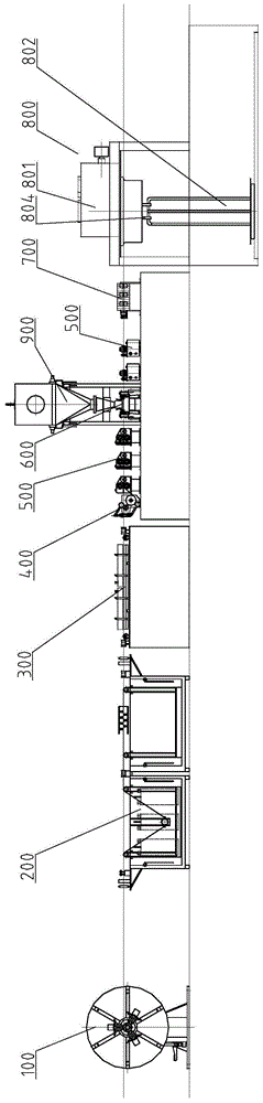
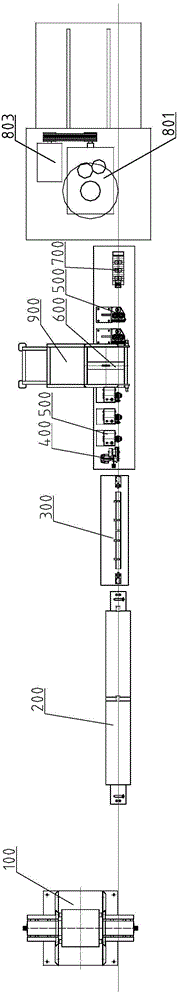
[0136] See Figures 15-16 , a flux-cored welding wire integrated molding machine set, including a tape unwinding machine 100, an ultrasonic cleaning device 200, a steel strip drying device 300, a molding machine, a speed-stabilizing traction device 801 at the exit of the molding machine, and a wire take-up device 802 arranged in sequence.

[0137] The above-mentioned molding machine is equipped with a steel strip speed measuring device 400, three horizontally installed passive rolling stands 500, a powder feeder 600 and its feeding system 900, three horizontally installed passive rolling stands 500 and rollers in order from the entrance to the exit. Die diameter reducing device 700.

[0138] The differences between this embodiment and Embodiment 1 are: 1) unwinding machine 100; 2) steel strip drying device 300; 3) steel strip speed measuring device 400; 4) passive rolling stand 500; 5) powder feeder 600 6) Stable speed traction device 801 and take-up device 802 at the exit of...

Embodiment 3

[0151] A method for producing flux-cored welding wire using the molding unit described in the above-mentioned embodiment 1 or embodiment 2, selecting a steel strip with a yield strength greater than 300Mpa, after the steel strip is released from the unwinding machine, it is cleaned by a cleaning device, and then Spray clean water on the running steel strip after cleaning to wash away the cleaning liquid on the surface of the steel strip, and then blow off most of the water on the surface of the steel strip through the air brush at the end of the ultrasonic cleaning tank. Then, the air brush at the front end of the steel strip drying device is used to flush the remaining water again, and then the infrared radiator irradiates the surface of the steel strip, and transfers the heat energy to the surface of the steel strip in the form of radiation, and bakes off the surface of the steel strip Remaining moisture that is difficult to remove by air blowing.

[0152] Use the steel belt...


PUM

PropertyMeasurementUnit
yield strengthaaaaaaaaaa
widthaaaaaaaaaa

Abstract

The invention discloses a flux cored wire integrated moulding machine set, comprising a strap releasing machine, a moulding machine and a wire winding device, wherein the moulding machine comprises a passive rolling frame, a moulding machine exit speed stabilizing device is arranged at the upstream of the wire winding device, and the moulding machine exit speed stabilizing device and the wire winding device share one power source. The invention also discloses a method for producing a welding wire by adopting the moulding machine set and the welding wire produced by adopting the method. By adopting the invention, the defect that the welding wire winding speed is interfered as the welding wire is wound on a flat cable disorderly and the radius is instantly instable when the welding wire is rolled can be avoided when a spool is used for winding the welding wire, and the unstable influence factor of a subordinate device of a speed stabilizing device to the speed stabilizing device is thoroughly eliminated. The moulding machine exit speed stabilizing device is adopted, and the output mode of speed is changed from an uncertain output mode to a long-term certain output mode, thus the stability of the operating speed of the moulding machine set is improved by one order of magnitude, the filling factor is ensured to be stable, and the product quality is improved.

Description

technical field [0001] The invention relates to the technical field of flux-cored welding wire production, in particular to a flux-cored welding wire integrated forming unit and a flux-cored welding wire production method. Background technique [0002] At present, if the main classification number is B23K35 / 40 (that is, the classification name is "manufacture of welding wire or electrode for brazing or welding") and the four words "flux-cored wire" appear in the instruction manual, it can be found in The invention patents that have been disclosed in China are as follows: 1) CN93115833.8, a rolling method for manufacturing flux-cored welding wire with discs; 2) CN96117079.4, a method for synchronously producing welding electrodes using ceramic production equipment; 3) CN97102700.5, welding wire Manufacturing process; 4) CN200410043645.X, automatic ceramic tubular wire material wire-making equipment and wire-making method; 5) CN200410097611.9, compatible method for manufacturi...

Claims


Application Information

Patent Timeline
Patent Type & Authority Patents(China)
IPC IPC(8): B23K35/40B23K35/02
CPCB21B1/16B21B13/02B21B31/10B21B31/22B21B38/00B21B2013/021B21B2015/0057B23K35/40
Inventor 张国良宋开泰刘继元李也庚陈春旺薛爱云
Owner TIANJIN SAINTEAGLE WELDING CO LTD
Why Eureka
Try Eureka