
Miniaturized on-chip antenna capable of resisting harmonic waves

An on-chip antenna and harmonic technology, applied in the direction of resonant antenna, slot antenna, mid-position feed between antenna endpoints, etc., to achieve the advantages of low price, solve the problem of process technology compatibility, and high integration effect

Inactive Publication Date: 2013-07-03
SHANGHAI JIAOTONG UNIV
View PDF1 Cites 0 Cited by
  • Summary
  • Abstract
  • Description
  • Claims
  • Application Information

AI Technical Summary

Problems solved by technology

[0002] With the development of high-speed and radio-frequency integrated circuits, the chip speed is getting higher and higher, and the area is getting smaller and smaller. However, the problems of parasitic resistance, parasitic capacitance and parasitic inductance of traditional metal interconnection lines are becoming more and more serious. The resulting RC delay, IR Pressure drop, CV 2 f Power consumption and crosstalk between lines will become bottlenecks restricting the development of high-speed circuits and radio frequency circuits

Method used


Image

  • Miniaturized on-chip antenna capable of resisting harmonic waves
  • Miniaturized on-chip antenna capable of resisting harmonic waves
  • Miniaturized on-chip antenna capable of resisting harmonic waves

Examples


Embodiment Construction

[0022] The embodiments of the present invention are described in detail below. This embodiment is implemented on the premise of the technical solution of the present invention, and detailed implementation methods and specific operating procedures are provided, but the protection scope of the present invention is not limited to the following implementation example.

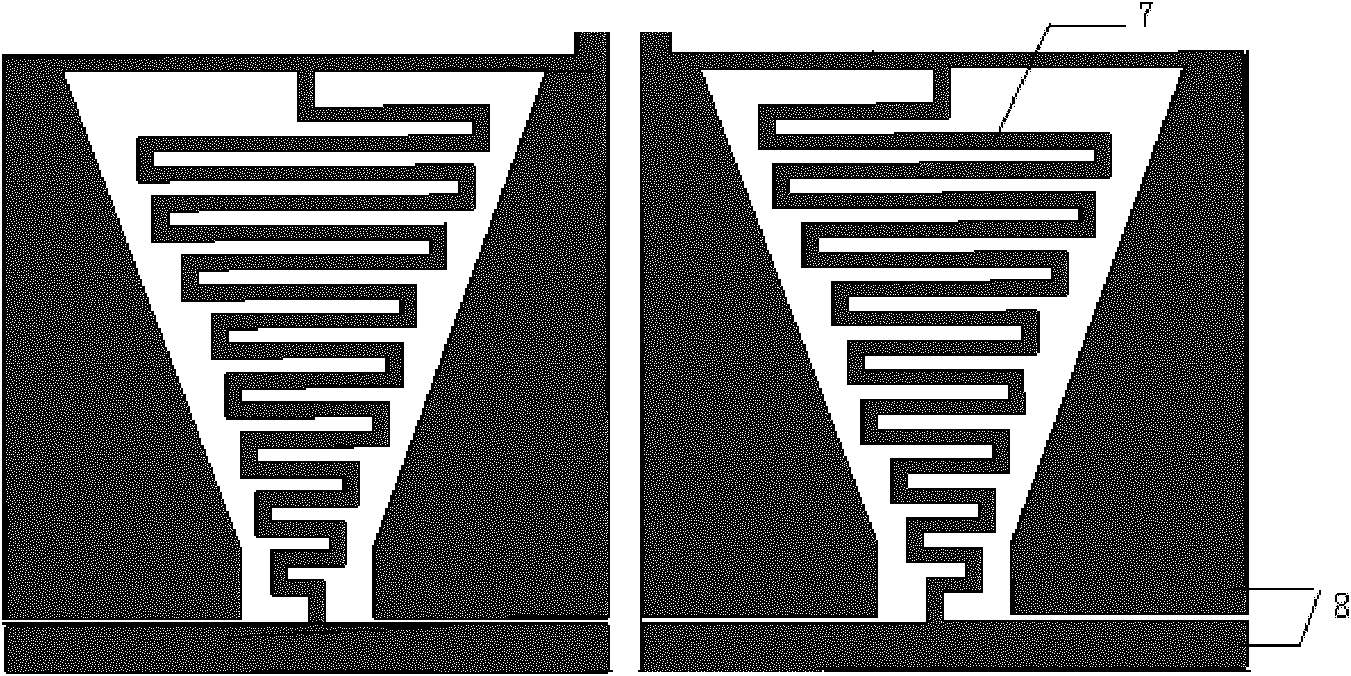
[0023] like figure 1 As shown, the chip silicon substrate 1 in this embodiment has a thickness of 300 μm and a resistivity of 10Ω·cm˜30Ω·cm. A silicon dioxide layer 2 with a thickness of 6 μm is grown on the silicon substrate for insulation; a metal top layer structure 3 for preparing an antenna is grown on the silicon dioxide layer.

[0024] The metal top layer structure 3 is the preparation layer of the on-chip antenna, and the thickness of the metal layer is 0.9 μm. On the metal layer, a suppressible third harmonic structure including an electromagnetic bandgap structure with wide stop band and miniaturization ...


PUM


Abstract

The invention discloses a miniaturized on-chip antenna capable of resisting harmonic waves, belonging to the technical field of wireless communication. The miniaturized on-chip antenna comprises a one-dimensional electromagnetic band gap structure and an on-chip dipole antenna, one end of the electromagnetic band gap is connected with the dipole antenna, the other end of the electromagnetic band gap is used as a differential feed end, and the electromagnetic band gap structure is of a one-dimensional differential slow wave structure and sequentially comprises a silicon substrate, a silicon dioxide and a metal top layer structure from the bottom up. The miniaturized on-chip antenna disclosed by the invention has higher integration property and can be prepared by adopting a standard CMOS (Complementary Metal Oxide Semiconductor) process and used for wireless interconnection for on-chip or chip-to-chip wireless data transmission.

Description

technical field [0001] The invention relates to a device in the technical field of wireless communication, in particular to a miniaturized on-chip antenna capable of suppressing harmonics. Background technique [0002] With the development of high-speed and radio-frequency integrated circuits, the chip speed is getting higher and higher, and the area is getting smaller and smaller. However, the problems of parasitic resistance, parasitic capacitance and parasitic inductance of traditional metal interconnection lines are becoming more and more serious. The resulting RC delay, IR Pressure drop, CV 2 f Power consumption and crosstalk between lines will become bottlenecks restricting the development of high-speed circuits and radio frequency circuits. Therefore, in recent years, wireless interconnection has been proposed as a solution to the limit problem of interconnection lines. For example, the on-chip wireless clock distribution system proposed and designed by B. A. Floyd ...

Claims


Application Information

Patent Timeline
Patent Type & Authority Patents(China)
IPC IPC(8): H01Q9/16H01Q13/10
Inventor 毛军发江亮
Owner SHANGHAI JIAOTONG UNIV
Learn More