Low profile cavity backed integrated antenna with widened frequency band

A widening frequency band and integrated antenna technology, applied in the microwave field, can solve the problems of high processing cost, narrow working bandwidth, and limited antenna application, and achieve the effect of reducing production cost and volume

Inactive Publication Date: 2011-08-03
HANGZHOU DIANZI UNIV
View PDF3 Cites 6 Cited by
  • Summary
  • Abstract
  • Description
  • Claims
  • Application Information

AI Technical Summary

Problems solved by technology

In order to improve the radiation characteristics of this type of antenna, providing an additional metal back cavity on this type of antenna unit can significantly improve the radiation characteristics of the antenna, but the traditional metal back cavity is large in size, difficult to process and high in processing costs, which damages the microstrip antenna or Advantages of slot antenna's low profile and easy integration
In recent years, the new type of cavity-backed antenna composed of substrate-integrated waveguide technology not only retains the low-profile and easy-to-integrate advantages of the microstrip antenna, but also retains the high radiation characteristics of the cavity-backed antenna, but is limited by the working principle. The working bandwidth is relatively narrow, which limits the application of this type of antenna

Method used


Image

  • Low profile cavity backed integrated antenna with widened frequency band
  • Low profile cavity backed integrated antenna with widened frequency band
  • Low profile cavity backed integrated antenna with widened frequency band

Examples


Embodiment Construction

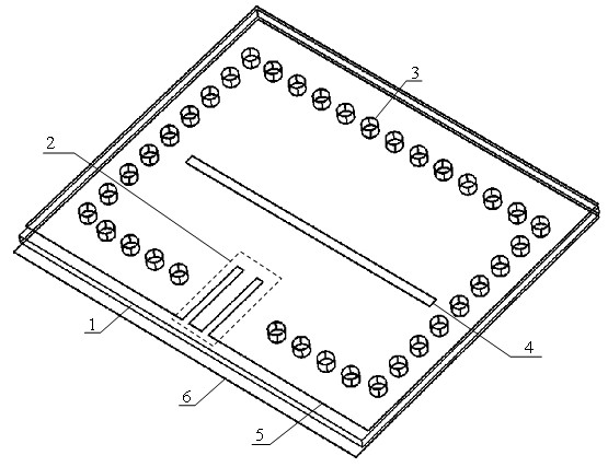
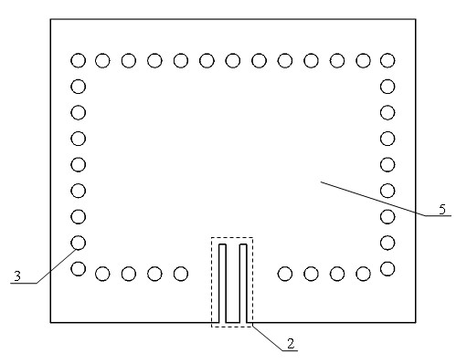
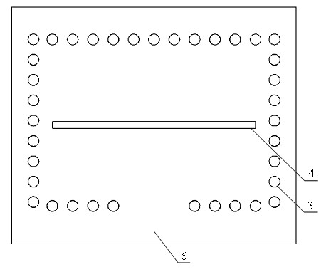
[0025] Such as figure 1 As shown, the low-profile cavity-backed integrated antenna with expanded frequency band includes a dielectric substrate 1 with a thickness of 0.5 mm. The dielectric substrate 1 has metal layers on both sides, which are metal layer 5 and metal layer 6, respectively. Through the dielectric substrate 1, the metal layer 5 and the metal layer 6 there is a through hole with a diameter of 1 mm, and the inner wall of the through hole is plated with metal to form an electrical interconnection unit 3. A plurality of electrical interconnection units 3 are arranged sequentially into an electrical interconnection array with rectangular outlines and rectangular sides of 17.8 mm and 12.3 mm, respectively. The electrical interconnection unit holes forming the electrical interconnection array have the same pitch, which is 1.5 mm. . The metal layer 5, the metal layer 6 and the area included in the electrical interconnection array form a rectangular cavity. Such as figur...


PUM


Abstract

The invention relates to a low profile cavity backed integrated antenna with a widened frequency band. A metal backed cavity of the traditional antenna has a large volume and high processing cost and is difficult to process. The low profile cavity backed integrated antenna with the widened frequency band comprises a dielectric substrate, an upper metal layer which is coated on the upper surface of the dielectric substrate, and a lower metal layer which is coated on the lower surface of the dielectric substrate. A plurality of electric interconnection units which pass through the upper metal layer, the dielectric substrate and the lower metal layer are arranged in sequence to form an electric interconnection array; an area which is surrounded by the upper metal layer, the lower metal layer and the electric interconnection array forms a cavity body; a feed unit stretches into the cavity body; and a linear type gap is formed on the metal layer inside the cavity body. The volume of the cavity backed antenna is reduced greatly, and an operation bandwidth of the low profile antenna of the type is reduced obviously at the same time; manufacturing cost is reduced remarkably; and seamless integration between the low profile cavity backed integrated antenna and a planar circuit can be realized.

Description

Technical field [0001] The invention belongs to the field of microwave technology, and relates to a low-profile cavity-backed integrated antenna with a wide frequency band, which can be used as a radio frequency transceiver front-end antenna, and is widely used in wireless communication systems such as mobile communications, satellite communications, and radar, and is particularly suitable for weak reception signals. Applications requiring high-gain antennas. Background technique [0002] As a key component of the communication system, antennas are widely used in wireless communication applications. The performance of the antenna directly determines the performance of the entire system. The high-performance antenna can not only significantly improve the performance of the system and obtain a good reception effect, but also can greatly alleviate the index pressure of the subsequent radio frequency circuit and reduce the cost of the system. Especially in space applications such a...

Claims


Application Information

Patent Timeline
Patent Type & Authority Applications(China)
IPC IPC(8): H01Q13/18
Inventor 罗国清李文钧江坤孙玲玲
Owner HANGZHOU DIANZI UNIV
Why Eureka
Try Eureka