
Pure water hydraulic through-shaft type spherical distribution axial plunger pump

An axial plunger pump and hydraulic technology, which is applied to liquid variable volume machinery, pumps, multi-cylinder pumps, etc., can solve the problems of unreported actual effects, complex structure of the distribution shaft cone, and difficult processing. Achieve the effect of simple structure, good self-positioning ability and less leakage

Inactive Publication Date: 2011-08-17
ZHEJIANG UNIV
View PDF9 Cites 27 Cited by
  • Summary
  • Abstract
  • Description
  • Claims
  • Application Information

AI Technical Summary

Problems solved by technology

Chinese patent (patent number: ZL00113140.0) discloses a plunger pump for low-viscosity fluid. The pressure formed during compression makes the thin-walled section of the plunger deform elastically in a drum shape, so that the outer surface of the plunger cast with resin material and the inner wall of the cylinder form a more effective sealing effect, but the actual effect has not been reported yet.
Chinese patent (patent number: ZL03118632.7) discloses an axial plunger water hydraulic pump, which adopts a full water lubricating valve flow distribution structure, the main shaft drives the swash plate to rotate, while the cylinder body is stationary, and the structure is relatively complicated. Difficult to process
Chinese patent (patent number: ZL2004118632.7) discloses an axial piston pump for water medium. Poor sex

Method used


Image

  • Pure water hydraulic through-shaft type spherical distribution axial plunger pump
  • Pure water hydraulic through-shaft type spherical distribution axial plunger pump
  • Pure water hydraulic through-shaft type spherical distribution axial plunger pump

Examples


Embodiment 1

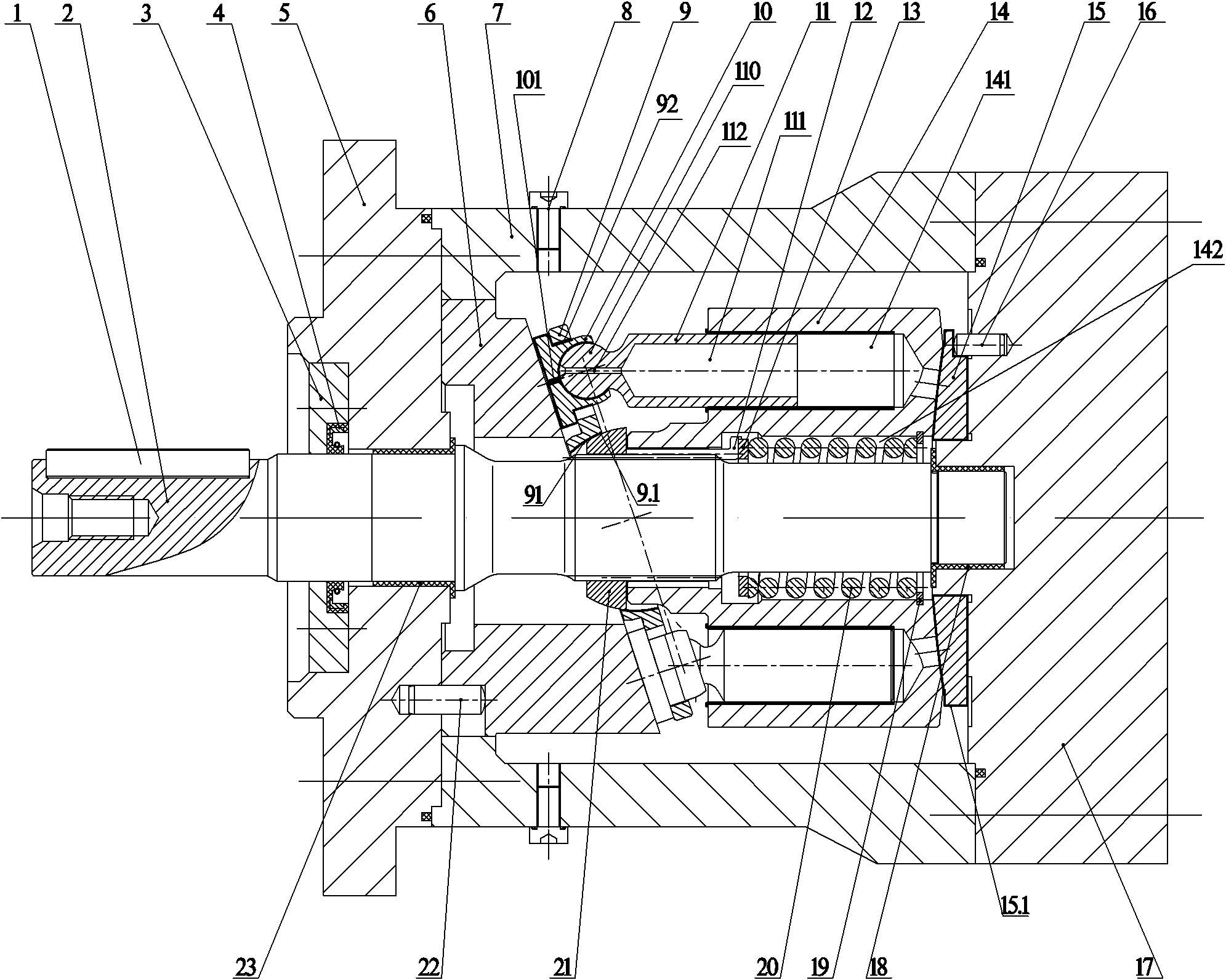
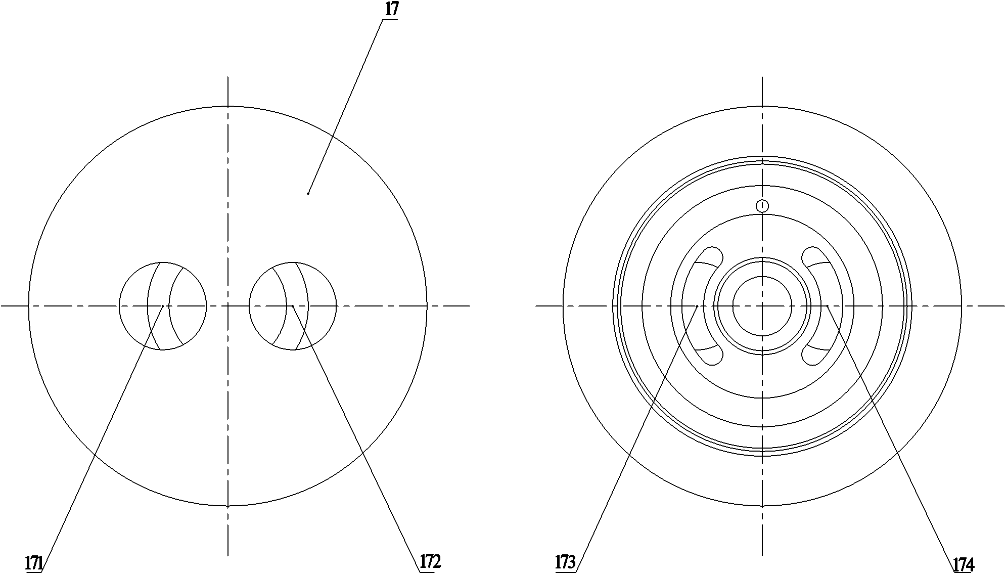
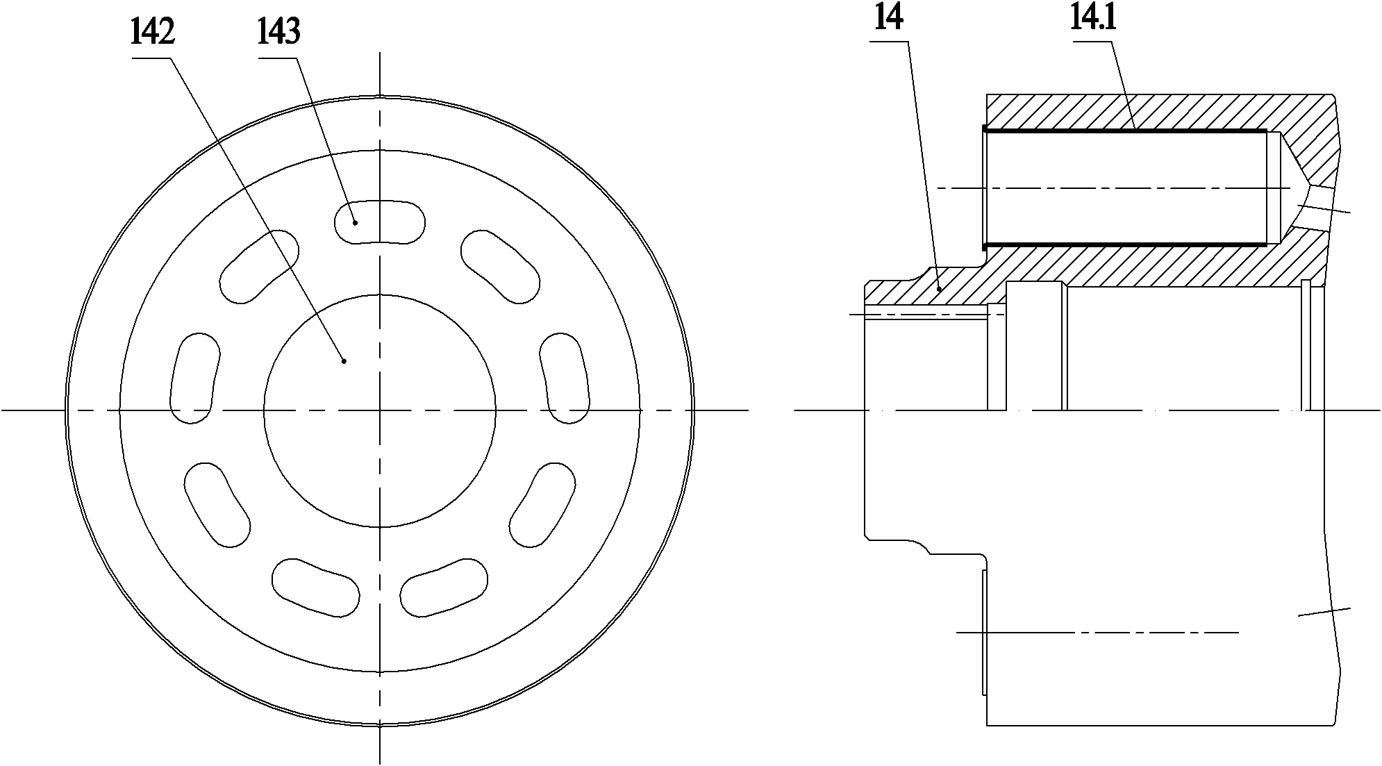
[0035] Embodiment 1, Figure 1~Figure 4 Combined with a pure water hydraulic shaft-through spherical distribution axial piston pump, it consists of a main shaft 2, a casing (composed of a front end cover 5, a housing 7 and a rear end cover 17), a cylinder body 14, and a plunger- Sliding shoe assembly (composed of plunger 11 and sliding shoe 10), swash plate 6, flow plate 15, ball hinge 21, return plate 9, center spring 20, front sliding bearing 23, rear sliding bearing 18, shaft seal 4 and shaft Covering 3 etc. constitutes. The casing 7 is provided with an exhaust screw 8 communicating with the inner cavity of the casing 7 , and the function of the exhaust screw 8 is to unscrew it during initial operation, so as to discharge residual air in the casing 7 .

[0036] A through-shaft structure is adopted, that is, the main shaft 2 runs through the front end cover 5, the housing 7 and the rear end cover 17 from left to right in turn; the main shaft 2 located on the left side of the ...


PUM


Abstract

The invention discloses a pure water hydraulic through-shaft type spherical distribution axial plunger pump which comprises a housing, wherein a through shaft type structure is adopted, a drive main shaft is connected with a cylinder body through a spline, and the cylinder body is provided with odd plunger holes; a plunger ball head and a slipper ball socket in each plunger-slipper assembly form a slipper spherical hinge pair, and plungers are respectively arranged in the plunger holes of the cylinder body to form a plunger pair; one end of a spring arranged in a center hole of the cylinder body is used for pressing the cylinder body on a distribution plate through a blocking ring, the distribution plate is positioned on a rear end cover through the center hole and a positioning pin, and the end face of the cylinder body and the distribution plate form a distribution pair; and the other end of the spring is used for pressing a slipper in each plunger-slipper assembly on a tilting tray through a pressing rod and the like, the end face of the slipper and the surface of the tilting tray form a slipper pair, and the outer spherical surface of a spherical hinge and the inner ball socket surface of a return tray form a center spherical hinge pair. When the main shaft is driven to rotate, the pure water hydraulic through-shaft type spherical distribution axial plunger pump can ensure that the plungers reciprocate along the plunger holes of the cylinder body and realize suction and discharge processes of sea water through the action of the distribution plate.

Description

technical field [0001] The invention relates to a power element used in pure water hydraulic transmission technology. Background technique [0002] The pure water hydraulic transmission technology that directly uses filtered natural water (including seawater and fresh water) as the working medium has the advantages of cleanliness, no pollution, and no fire hazard. In recent years, with the application of new engineering materials and the development of advanced manufacturing technology , The in-depth study of pure water hydraulic transmission theory, Western developed industrial countries have made pure water hydraulic transmission technology out of the laboratory, developed commercial products, widely used in food, paper, textile, medical equipment, fire protection, metallurgy, mining, atomic energy Power plants, marine development and other fields. However, my country has started research on pure water hydraulic transmission technology since the early 1990s, but the devel...

Claims


Application Information

Patent Timeline
IPC IPC(8): F04B1/22
Inventor 周华翟江罗凯金聪杨华勇
Owner ZHEJIANG UNIV
Learn More