Wireless charging and power supply method for wireless sensor network node

A wireless sensor and sensor network technology, applied in the field of sensor networks, can solve the problems of wireless sensor networks that are not suitable for the random distribution of nodes, high power, etc., and achieve the effects of avoiding no-load energy waste, improving life expectancy, and increasing angles

Inactive Publication Date: 2011-08-17
SOUTHEAST UNIV
View PDF3 Cites 46 Cited by
  • Summary
  • Abstract
  • Description
  • Claims
  • Application Information

AI Technical Summary

Problems solved by technology

However, whether it is a small electrical appliance or a large electric vehicle, the widely used charging and supply method is electromagnetic near-field coupling. The transmitting coil and the receiving coil are close to each other (generally millimeter or centimeter level), which is obviously not suitable for wireless networks with randomly distributed nodes. Sensor Networks
Moreover, the wireless charging and power supply equipment of electric vehicles and home appliances generally have high power, and the sensor nodes are all low-power electronic devices, so it is not possible to directly introduce the existing wireless charging and power supply equipment into the field of wireless sensor networks

Method used


Image

  • Wireless charging and power supply method for wireless sensor network node
  • Wireless charging and power supply method for wireless sensor network node
  • Wireless charging and power supply method for wireless sensor network node

Examples


Embodiment Construction

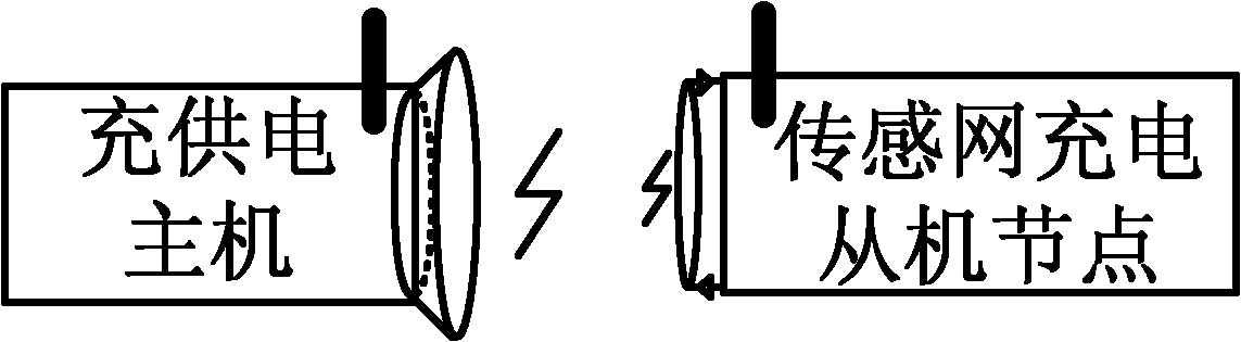
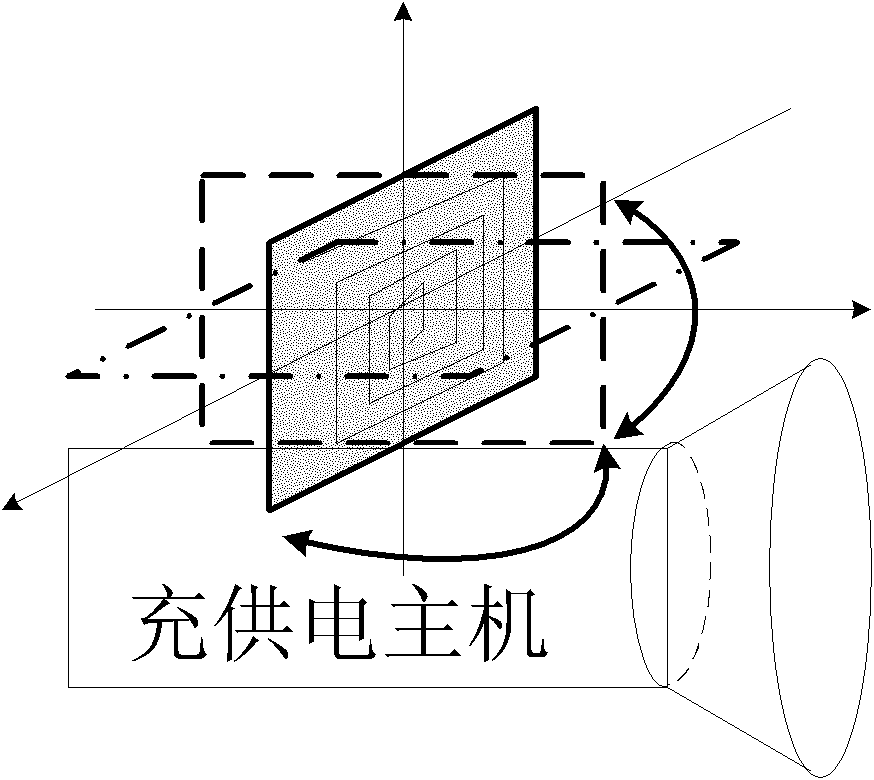
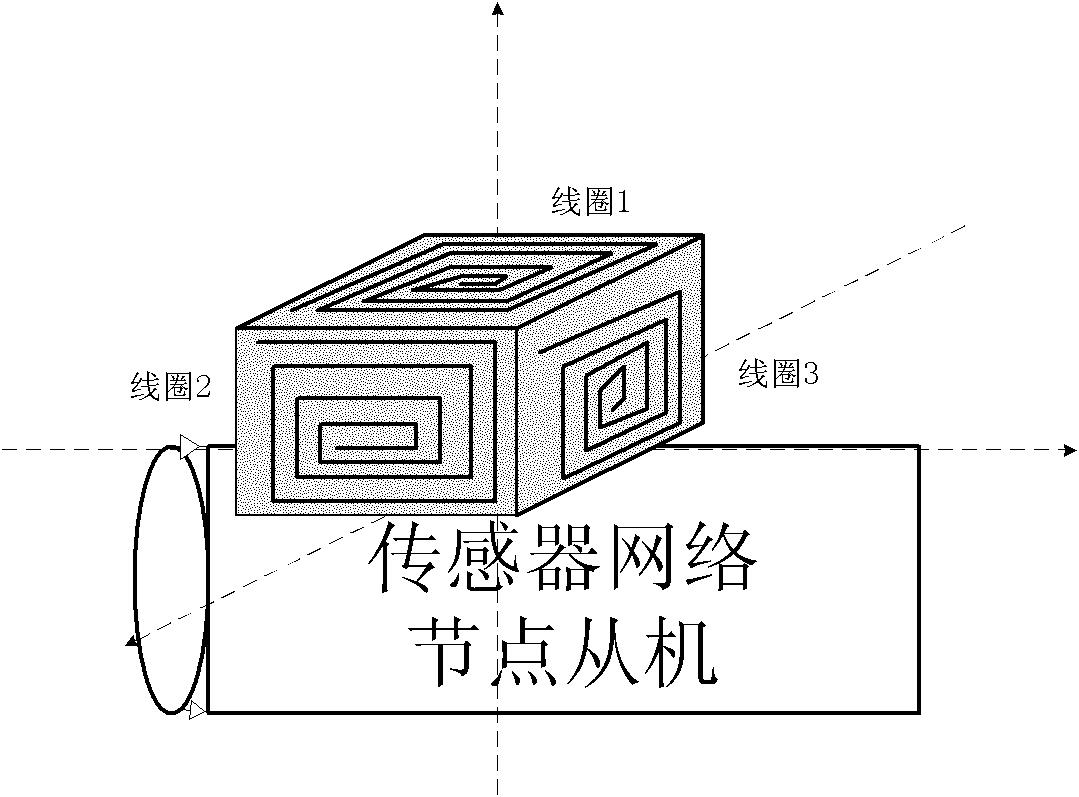
[0031] figure 1 The wireless sensor network power transmission system composed of a charging and supplying host and a sensor network node charging and supplying slave used in the method of the present invention, the charging and supplying host such as figure 2 , 4 As shown in , 9, it contains a control processor, a controllable scanning frequency source, a rotatable transmitting antenna and a wireless communication module. The control processor (MCU) adopts a low-power processor with an AD module. The controllable scanning frequency source is a voltage-controlled oscillator (VCO). Changing the input voltage can change the frequency of the oscillator output signal. When the input voltage is a constant DC When the voltage is high, it is a stable oscillator, and when the input voltage is a triangle wave or a sawtooth wave, it becomes a scanning frequency source. Such as Figure 12. In the charging and power supply host circuit, the modulation voltage of the controllable scan...


PUM


Abstract

The invention discloses a wireless charging and power supply method for a wireless sensor network node. A wireless electrical energy transmission system consisting of a charging and power supply host and a node charging and power supply slave is involved, wherein the charging and power supply host is provided with an energy transmission circuit which has adjustable transmission frequency and power, measurable transmission current and a rotary transmission antenna; and the node charging and power supply slave is provided with a wireless coupling receiving circuit, a multidirectional coupling receiving antenna, a charging and power supply voltage detection circuit and a booster circuit. Optimal coupling frequency and optimal transmission power between the transmission circuit and the receiving circuit are found by scanning the transmission frequency and detecting the detection current, an optimal coupling direction between the transmission antenna and the receiving antenna is found by rotating a charging and power supply antenna, and charging and power supply information is exchanged by a wireless communication channel to determine whether charging and power supply are required or not between the host and the slave and determine charging and power supply frequency and power and the direction of the transmission direction. Therefore, the wasting of idle energy sources is avoided when the slave is not charged and supplied with power, and high wireless charging and power supply efficiency, long wireless charging and power supply distance and high wireless charging and power supply speed are ensured.

Description

technical field [0001] The invention relates to wireless charging and power supply technology for electrical equipment, in particular to a wireless charging and power supply method for wireless sensor network nodes, which belongs to the technical field of sensor networks. Background technique [0002] The rapid development of sensor technology, electronic technology, wireless communication technology and low-power embedded technology has given birth to Wireless Sensor Networks (WSN), and with its low power consumption, low cost, distributed and self-organizing characteristics Bringing about a revolution in information perception. A wireless sensor network is a network composed of sensor nodes that can monitor, perceive and collect various information (such as light intensity, temperature, humidity, noise and harmful gas concentration) of objects of interest to observers in the node deployment area in real time. and other physical phenomena), and the information is processed...

Claims


Application Information

Patent Timeline
Patent Type & Authority Applications(China)
IPC IPC(8): H02J17/00H02J7/00H02J50/12
CPCY02B40/90Y02B60/50
Inventor 吴剑锋李建清李小敏王佚楠李健楠杜莉唐健李蓬勃刘弘逸李冬
Owner SOUTHEAST UNIV
Why Eureka
Try Eureka