High-accuracy electromagnetic force controlled linear motor and control system thereof

A technology for controlling straight lines and control systems, applied in control systems, AC motor control, propulsion systems, etc., can solve problems such as easy oscillation and overshoot, weak anti-disturbance ability, etc., and achieve low oscillation and overshoot, anti-disturbance capabilities Strong, improve the effect of current control frequency response

Active Publication Date: 2011-08-17
HARBIN INST OF TECH
View PDF3 Cites 8 Cited by
  • Summary
  • Abstract
  • Description
  • Claims
  • Application Information

AI Technical Summary

Problems solved by technology

[0004] The present invention solves the contradiction between the large driving force required for acceleration and deceleration of the traditional linear motor and the small driving force and high resolution required for uniform motion or positioning control, and the anti-disturbance ability of the motor in the case of sudden acceleration or external disturbance. Weak, prone to oscillation and overshoot problems; and the proposed high-precision electromagnetic force control linear motor and its control system

Method used


Image

  • High-accuracy electromagnetic force controlled linear motor and control system thereof
  • High-accuracy electromagnetic force controlled linear motor and control system thereof
  • High-accuracy electromagnetic force controlled linear motor and control system thereof

Examples


specific Embodiment approach 1

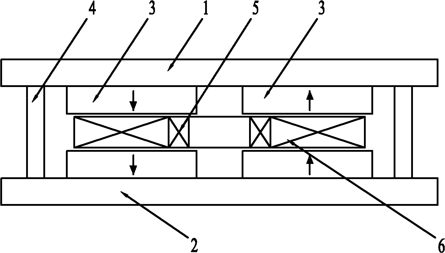
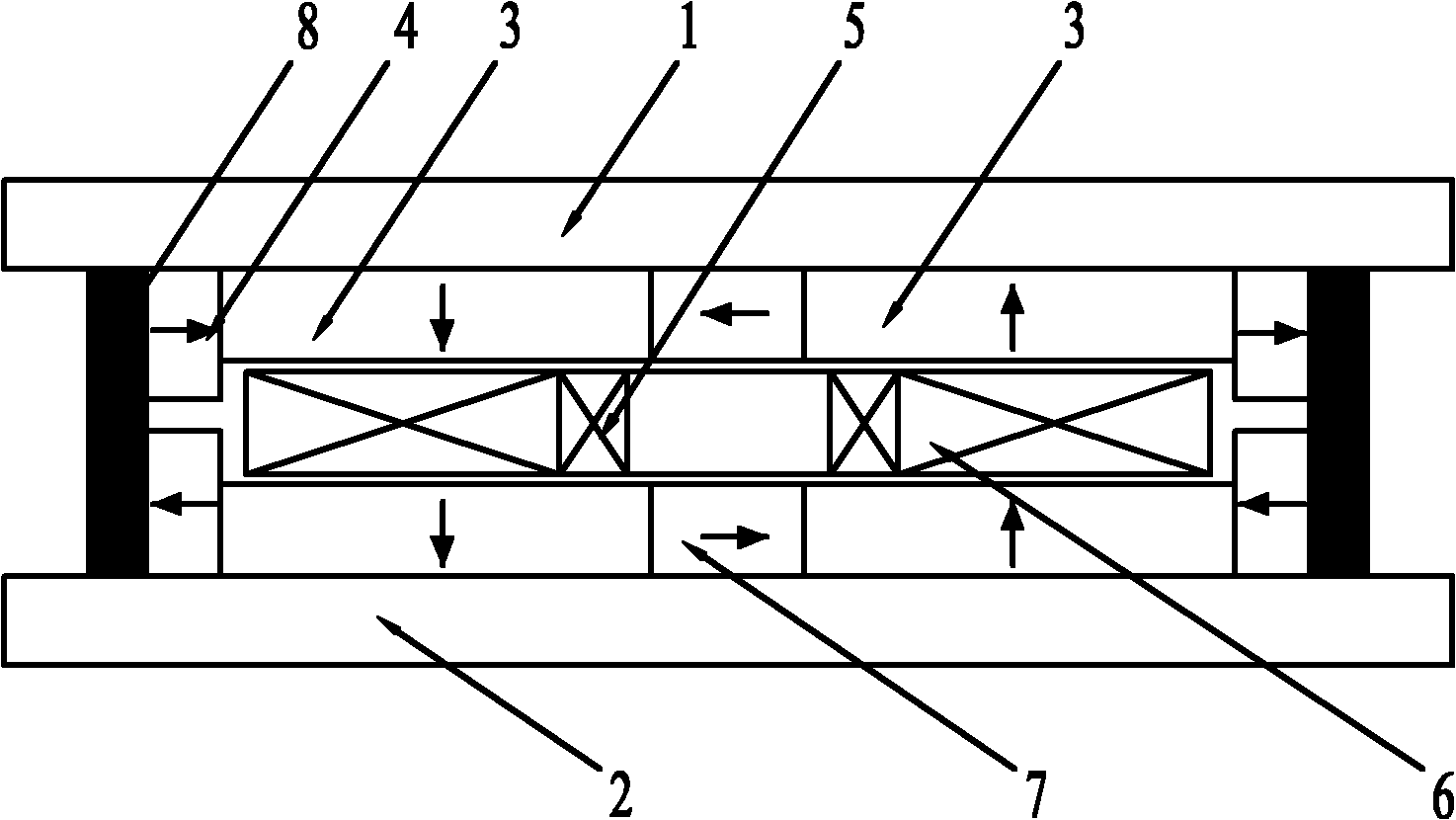
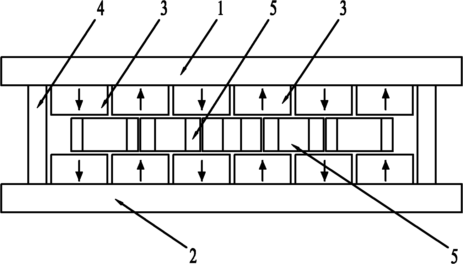
[0017] Specific implementation mode one: combine figure 1 To illustrate this embodiment, the high-precision electromagnetic force control linear motor in this embodiment includes a primary and a secondary; an air gap is left between the primary and the secondary;

[0018] The secondary is composed of a plurality of permanent magnet units with the same structure, an upper magnetic yoke 1 and a lower magnetic yoke 2;

[0019] Each permanent magnet unit is composed of four main permanent magnets 3 and two elongated auxiliary permanent magnets 4;

[0020] The two main permanent magnets 2 are planar permanent magnets magnetized in parallel;

[0021] The four main permanent magnets 3 are equally divided into an upper main permanent magnet group and a lower main permanent magnet group;

[0022] The upper main permanent magnet group is fixedly arranged on the lower surface of the upper magnetic yoke 1; the lower main permanent magnet group is fixedly arranged on the upper surface of...

specific Embodiment approach 2

[0033] Specific implementation mode two: combination Figure 4 This embodiment is described. This embodiment is a control system that adopts the high-precision electromagnetic force control linear motor described in Embodiment 1. It is composed of a high-precision electromagnetic force control linear motor and a plurality of identical drive control units;

[0034] The high-precision electromagnetic force controls the primary armature winding of each phase of the linear motor to draw three taps; each of the drive control units is respectively installed on the primary phase of the armature winding of the linear motor; each of the A drive control unit is made up of four drive controllers 9;

[0035] The two control output terminals of the first drive controller are respectively connected to the head end and the tail end of a phase armature winding; the two control output terminals of the second drive controller are respectively connected to the first tap of a phase armature windi...

specific Embodiment approach 3

[0036] Specific implementation mode three: combination Figure 5 This embodiment is described. This embodiment is a control system that adopts the high-precision electromagnetic force control linear motor described in Embodiment 1. It is composed of a high-precision electromagnetic force control linear motor and a plurality of identical drive control units;

[0037] The high-precision electromagnetic force controls the primary armature winding of each phase of the linear motor to draw three taps; each of the drive control units is respectively installed on the primary phase of the armature winding of the linear motor; each of the A drive control unit is made up of drive controller 9 and four switch 10;

[0038] A control output terminal of the drive controller is respectively connected with the head end of a phase armature winding, the first tap of a phase armature winding, the second tap of a phase armature winding and a phase electric current through four switch 10. The thi...


PUM


Abstract

The invention discloses a high-accuracy electromagnetic force controlled linear motor and a control system thereof, which relate to the linear motor and the control system thereof and aim to solve the problems of the conventional linear motor that the requirements of high driving forces in acceleration and deceleration are conflicted with the requirements of weak driving forces and high resolution in uniform motion or positioning control and that the motor has low disturbance resistance and easily produces oscillation and overshooting under the condition of acceleration abrupt change or external disturbance. An air gap is reserved between a primary part and a secondary part. The secondary part consists of a plurality of permanent magnet units with the same structure, an upper magnetic permeable yoke and a lower magnetic permeable yoke. The primary part is a multi-phase armature winding, wherein each phase of armature winding consists of a plurality of coils which are connected in series; and the two active sides of each of inner coils and outer coils are positioned between main permanent magnets which are arranged opposite in the permanent magnet units respectively. The control system consists of the linear motor and a plurality of drive control units. The linear motor has the advantages of high disturbance resistance and low oscillation and overshooting rate under the condition of the acceleration abrupt change or external disturbance.

Description

technical field [0001] The invention relates to a linear motor and its control system. Background technique [0002] In the field of modern processing industry, many occasions such as laser cutting, high-speed grinding machines, precision lathes, machining centers, etc. require high-speed and high-precision linear motion, while traditional methods can only be obtained by means of intermediate links such as rotating motors and ball screws. Linear motion, which inevitably has disadvantages such as large inertia, large friction, and backlash. In recent years, with the advancement of linear motor technology, more and more occasions have begun to directly apply it to obtain linear motion. Due to the direct drive technology, the linear motor has the advantages of fast speed, high acceleration, high positioning accuracy, long stroke and fast dynamic response, which just meet the requirements of high-speed precision machining technology. [0003] However, the traditional linear mo...

Claims


Application Information

Patent Timeline
Patent Type & Authority Applications(China)
IPC IPC(8): H02K41/02H02P25/06
Inventor 寇宝泉刘奉海李立毅潘东华
Owner HARBIN INST OF TECH
Why Eureka
Try Eureka