High-frequency waveguide and phase shifter using same, radiator, electronic device which uses this phase shifter and radiator, antenna device, and electronic device equipped with same

An antenna device and high-frequency wave technology, applied to a high-frequency waveguide, a phase shifter using the high-frequency waveguide, a radiator, an electronic device using the phase shifter and the radiator, an antenna device, and an electronic device equipped with the antenna device It can solve the problems of large-scale, large-scale, and large antenna body of the antenna device.

Inactive Publication Date: 2011-08-17
PANASONIC CORP
View PDF10 Cites 34 Cited by
  • Summary
  • Abstract
  • Description
  • Claims
  • Application Information

AI Technical Summary

Problems solved by technology

[0015] In addition, the above-mentioned conventional example has a problem of increasing the size of the antenna device.
That is, in order to obtain the above-mentioned large detection angle of about 15 degrees left and right in the

Method used


Image

  • High-frequency waveguide and phase shifter using same, radiator, electronic device which uses this phase shifter and radiator, antenna device, and electronic device equipped with same
  • High-frequency waveguide and phase shifter using same, radiator, electronic device which uses this phase shifter and radiator, antenna device, and electronic device equipped with same
  • High-frequency waveguide and phase shifter using same, radiator, electronic device which uses this phase shifter and radiator, antenna device, and electronic device equipped with same

Examples


no. 1 approach

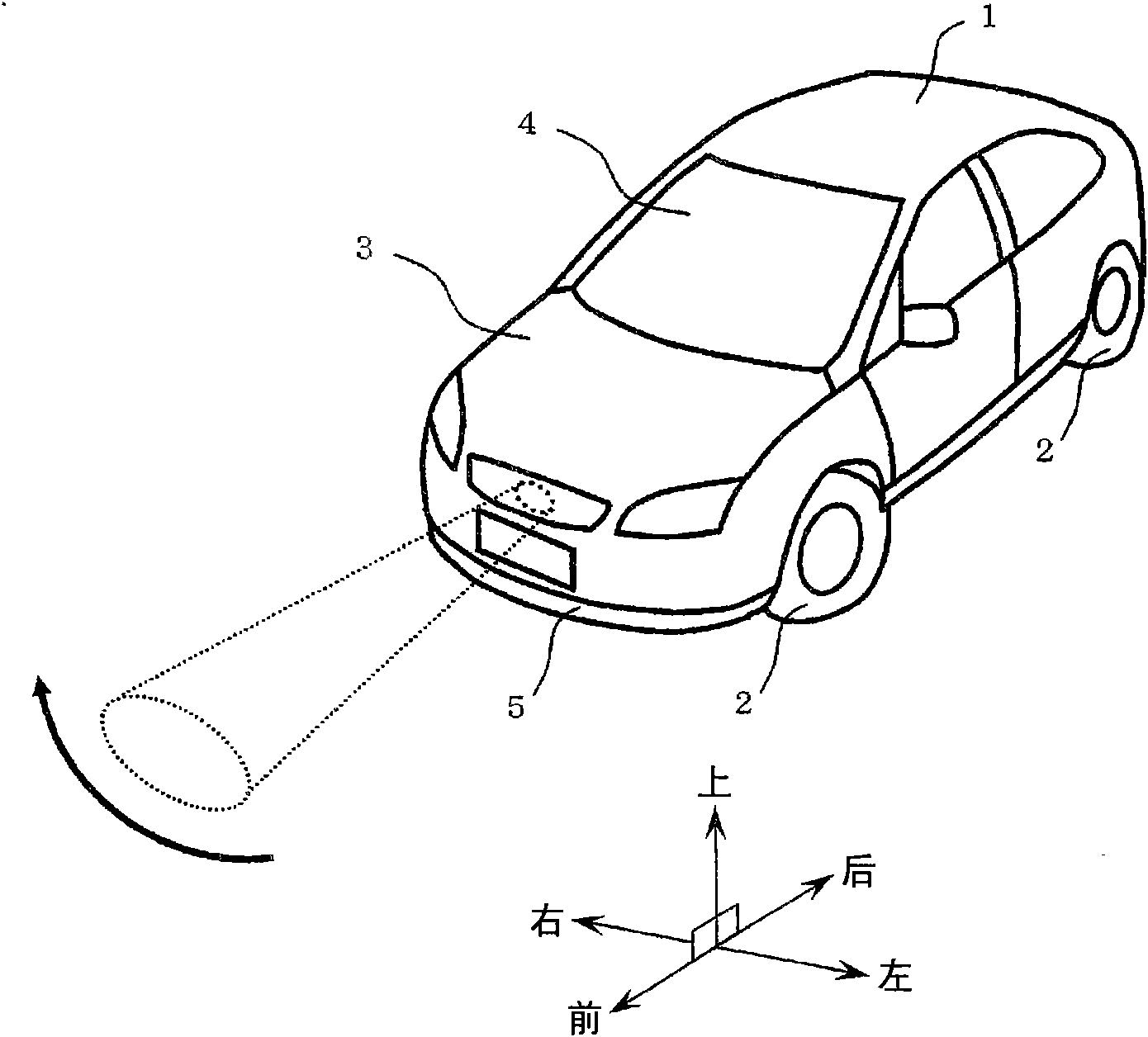
[0051] figure 1 Among them, 1 is a car body, and four tires 2 are arranged under the car body 1 .

[0052] These tires 2 are rotationally driven by an engine (not shown) housed under a hood 3 of the vehicle body 1 .

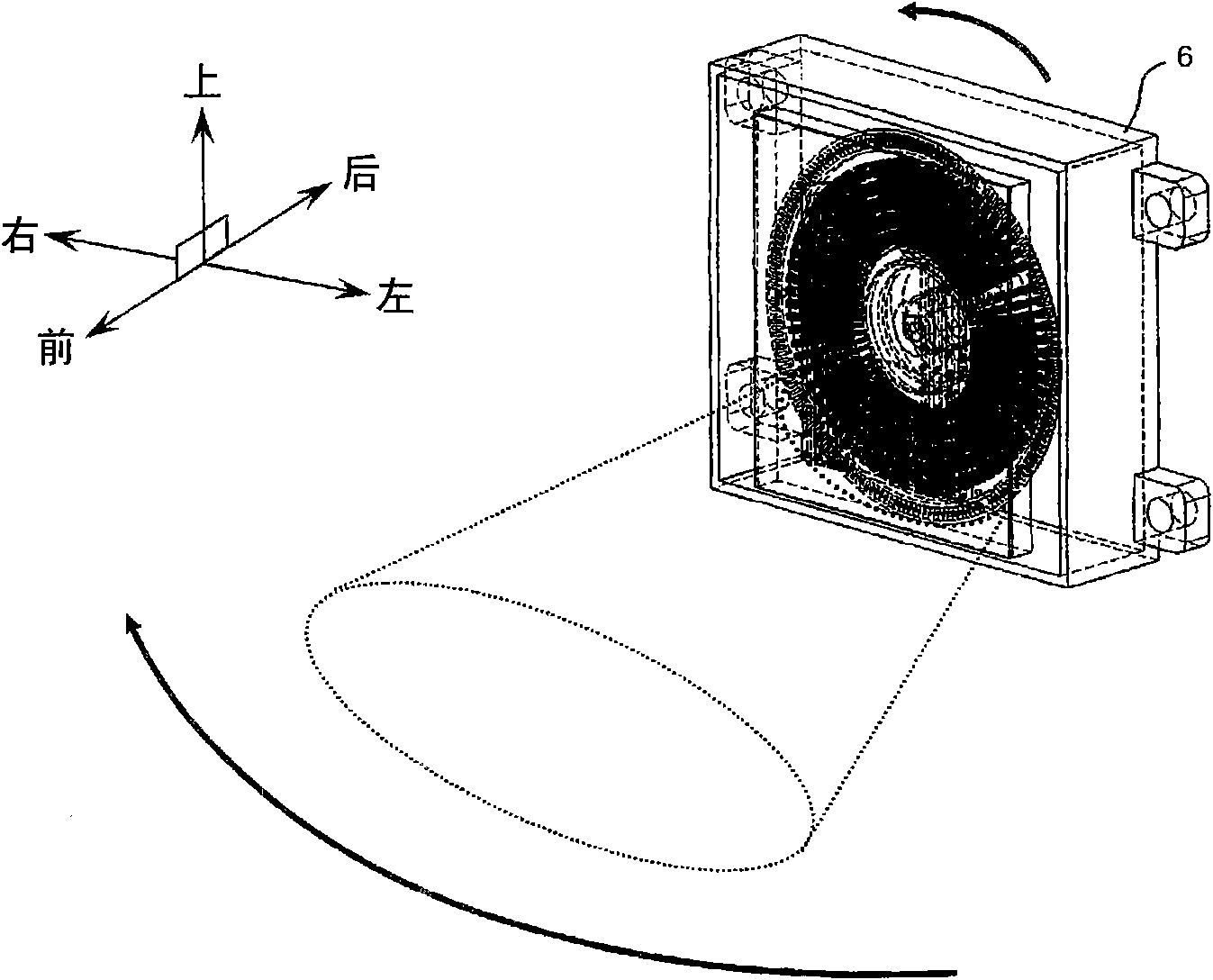
[0053] In addition, a steering wheel (not shown) for operating the tires 2 is provided in the vehicle compartment 4 . In addition, above the shock absorber 5 on the front side of the automobile main body 1, a device such as figure 2 Antenna assembly 6 is shown.

[0054]As far as this antenna device 6 is concerned, it will be described in detail later, but as these figure 1 , figure 2 As shown, on the front side of the car body 1, relative to the range in front (for example, 150 meters), in the range from the center along the horizontal direction (for example, 15 degrees (total 30 degrees)), the 76.5 GHz radio waves are sequentially arranged according to their angles. Transmit while scanning. In addition, the antenna device 6 detects objects (obstacles suc...

other Embodiment approach

[0149] (A)

[0150] The above shows that the suppression of electric waves to figure 1 The stray antenna device in the unwanted direction of the left and right directions. However, the present invention is not limited thereto. For example, it can also suppress the electric wave to figure 1 The stray antenna device in the unwanted direction of the up and down directions.

[0151] Here, a device for improving recognition accuracy of a vehicle-mounted radar when the antenna device 6 according to the present embodiment is used for a vehicle-mounted radar will be described below.

[0152] Figure 23 It is a perspective view of a high-frequency waveguide in which the height of the bump 95 changes periodically. Figure 24 is a wavelength characteristic diagram of a high-frequency waveguide whose bulge height changes periodically. Figure 25 It is a perspective view of a radiator using a high-frequency waveguide whose bump height changes periodically. Figure 26 is the directiv...


PUM


Abstract

The invention refers to a high-frequency waveguide and a phase shifter using the same, a radiator, an electronic device which uses this phase shifter and a radiator antenna device, and an electronic device equipped with the same. This high-frequency waveguide is formed by first/second conductors (22, 23) which are arranged facing each other with an interval of less than lambda 0/2 when the free space wavelength of the operating frequency of the high-frequency signal is lambda0. In a waveguide-forming part between these first/second conductors (22, 23), a ridge (25) which protrudes from one toward the other of the first/second conductors (22, 23) and which is formed by extending along the waveguide-forming part is provided. Multiple columnar protrusions (24) with a height of lambda0/4 are arranged with an interval of less than lambda0/2 on at least one of the first/second conductors (22, 23) outside of the aforementioned waveguide-forming part and lateral to the ridge (25).

Description

technical field [0001] The present invention relates to a high-frequency waveguide, a phase shifter using the high-frequency waveguide, a radiator, an electronic device using the phase shifter and the radiator, an antenna device, and an electronic device including the antenna device. Background technique [0002] A high-frequency waveguide used as a high-frequency energy transmission line is constructed by combining first and second waveguide constituents. [0003] Specifically, the high-frequency waveguide is constituted by integrating the first and second waveguide structures respectively provided with grooves in a state where the openings of the grooves coincide. In addition, there is Patent Document 1 (Japanese Unexamined Patent Publication No. 2004-48486 ) as a prior document similar to this. [0004] Prior art literature [0005] Patent Document 1: Japanese Unexamined Patent Publication No. 2004-48486 [0006] Patent Document 2: Japanese Patent Laid-Open No. 2002-22...

Claims


Application Information

Patent Timeline
IPC IPC(8): H01Q3/30G01S7/02G01S7/03H01P1/18H01P3/12H01Q1/40H01Q13/10H01Q21/06
CPCG01S7/032H01Q21/061H01Q1/3233G01S2013/9375H01Q1/3291H01Q21/0006H01Q3/32H01Q13/10H01P3/123H01P1/182G01S2013/93271
Inventor 桐野秀树山本功渡部昌史
Owner PANASONIC CORP
Why Eureka
Try Eureka