Device and method for measuring spatial free attitude of rigid object, and method for analyzing data

A technology of object space and measuring device, which is applied in the direction of measuring device, optical device, static/dynamic balance test, etc., can solve the problems of low measurement accuracy, complicated instrument structure, and inability to meet simultaneous measurement, etc., to simplify the measuring device, The effect of high measurement accuracy

Inactive Publication Date: 2012-09-05
INST OF FLUID PHYSICS CHINA ACAD OF ENG PHYSICS
View PDF0 Cites 0 Cited by
  • Summary
  • Abstract
  • Description
  • Claims
  • Application Information

AI Technical Summary

Problems solved by technology

For example, laser interferometry has the advantages of high measurement accuracy, but the detection process is complicated, the environmental requirements are high, and the requirements for users are also high, and it is a single-parameter measurement, which cannot meet the requirements of simultaneous measurement of six degrees of freedom; The visual measurement method of the CCD camera system uses the CCD as a receiver to scan a specific model placed on the object to be measured to obtain visual signals of the feature points on the model, and obtain the individual points of the object to be measured through a certain algorithm. degrees of freedom information
The characteristic of this system is that it needs to calibrate multiple CCD cameras arranged according to strict requirements. The installation and adjustment of CCD cameras are difficult, the calibration work is quite complicated, and the requirements for users are also quite high, and the whole system is sensitive to vibration. The structure is complex, the cost is high, and it is not easy to miniaturize. The accuracy is related to the CCD camera system, and the accuracy has a great relationship with the cost. In principle, the position measurement in the height direction and the roll angle measurement in the axial direction are determined to have low accuracy.
The PSD-based measurement method only has high accuracy in a small area in the center, and when the measurement range is extended, the measurement accuracy will decrease

Method used


Image

  • Device and method for measuring spatial free attitude of rigid object, and method for analyzing data
  • Device and method for measuring spatial free attitude of rigid object, and method for analyzing data
  • Device and method for measuring spatial free attitude of rigid object, and method for analyzing data

Examples


Embodiment Construction

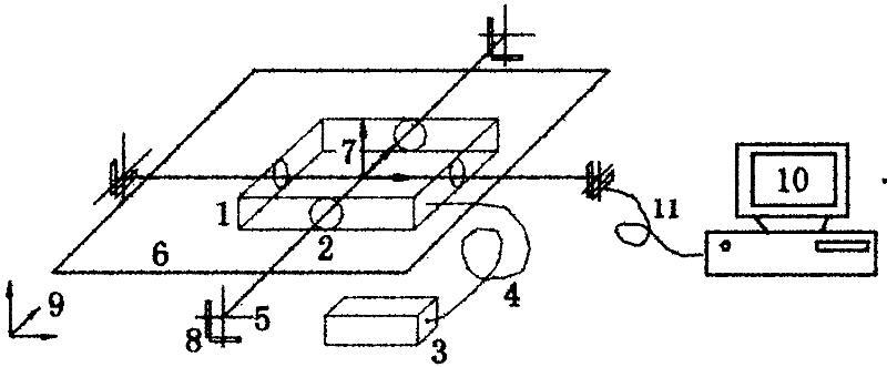
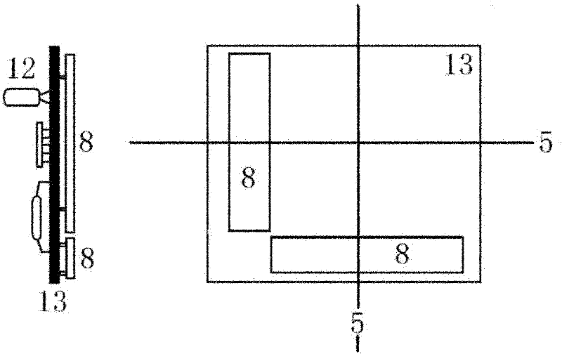
[0029] see Figure 1~3 .

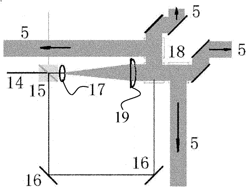
[0030] The cross indicates the generation of ray 5: at image 3 In , the laser beam generated by the laser 3 is input into the optical system through the transmission fiber 4 . First, the beam splitting prism 15 is divided into two mutually perpendicular laser beams, one of which is expanded by the beam expander 17 into a laser beam with a required width, and then focused by the corresponding cylindrical mirror 19 into linear light rays in the vertical direction. After being output by the dichroic prism group 18 and the reflector, the linear light in the vertical direction in the four directions in the plane is obtained. Secondly, the laser beam in another direction is expanded by a beam expander (not shown in the figure), and then focused into a linear line of light in the horizontal direction by a corresponding cylindrical mirror (not shown in the figure), which is reflected The mirror 16 is input to the dichroic prism group 18 for light synthes...


PUM


Abstract

The invention discloses a device and a method for measuring a spatial free attitude of a rigid object, and a method for analyzing data, and relates to a measurement technology. The device comprises a planar orthogonal four-directional cursor generation device and a linear array charge coupled device (CCD); and the linear array CCD is provided with a data output interface. In the invention, a position detector consists of a plurality of linear array CCDs, so the problem that a detector with a large planar array position cannot be substituted is solved, the measurement device is simplified and the same measurement precision within a measurement range can be guaranteed. By adoption of the method for processing the data, the measurement of a linear light position can reach the subpixel level under the condition of poor data quality; and finally, a systematic measurement result can reach a higher level.

Description

technical field [0001] The invention relates to measurement technology. Background technique [0002] The six-degree-of-freedom parallel platform is an important simulation test equipment for dynamic reliability research of various equipment such as aircraft, ships, and vehicle-mounted instruments. Its research is a precise and complex engineering science, involving machinery, computer control, and photoelectric measurement. and other technologies. The attitude measurement of the six-degree-of-freedom parallel platform is a typical multi-degree-of-freedom attitude measurement. The measurement objects are the amount of space movement and the amount of rotation around the space axis. Through the measurement of these parameters and inverse solution, the correct space attitude parameters of the platform can be obtained. , feedback to the control system can control it, so as to achieve the purpose of changing its attitude according to the requirements. [0003] There are many f...

Claims


Application Information

Patent Timeline
Patent Type & Authority Patents(China)
IPC IPC(8): G01B11/00G01B11/02G01B11/26G01C11/00G01M1/12
Inventor 江孝国李洪杨兴林文龙石金水张开志李劲王远
Owner INST OF FLUID PHYSICS CHINA ACAD OF ENG PHYSICS
Why Eureka
Try Eureka