Stud gear with cutting edge and drill thereof

A cutting edge and column tooth technology, applied in drill bits, drill pipes, drill pipes, etc., can solve the problems of arranging slag discharge grooves to discharge slag or temporarily storing gravel, aggravating the wear of the steel carcass of the drill bit, and speeding up the wear speed of the column teeth.

A cutting edge and column tooth technology, applied in drill bits, drill pipes, drill pipes, etc., can solve the problems of arranging slag discharge grooves to discharge slag or temporarily storing gravel, aggravating the wear of the steel carcass of the drill bit, and speeding up the wear speed of the column teeth.

CN102168526AInactive Publication Date: 2011-08-31李荟敏

Image

  • Stud gear with cutting edge and drill thereof
  • Stud gear with cutting edge and drill thereof
  • Stud gear with cutting edge and drill thereof

Examples


Embodiment Construction

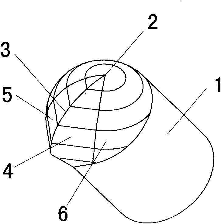
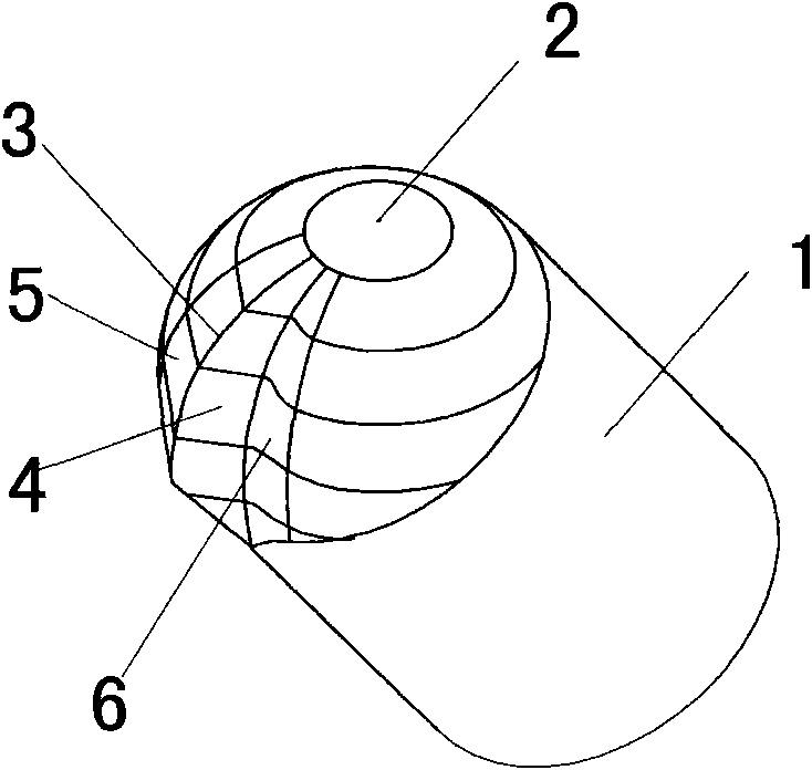
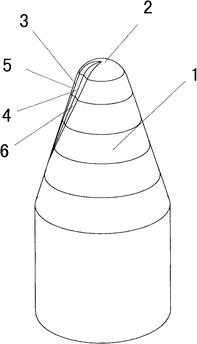
[0009] Such as figure 1 Shown is a side view of the ball stud gear shaft with a large cutting edge of the present invention, and its placement orientation is roughly the same as its installation orientation on the down-the-hole drill bit, that is, the impact head 2 faces upward, and the blade front 4 faces the reader , the same below, see Figure 17 . Among them, 1 is a column tooth, and its root shape is a cylinder; 2 is an impact head, which directly contacts the bottom of the well and breaks rock by impact when working on the down-the-hole drill bit; 3 is a cutting edge, which is in the When the down-the-hole bit rotates and works, it directly contacts the protruding corner of the well wall and breaks the rock by cutting; 4 is the front of the blade; The difference from the usual hemispherical head of the column tooth is that it is provided with a front edge 4 and a rear edge 5 that are gradually raised relative to the generatrix of the outer surface of the column tooth r...


PUM


Abstract

The invention discloses a stud gear with a cutting edge and a drill thereof, and is suitable for manufacturing a stud gear with a cutting edge and the drill of the stud gear which are used for drilling operations for getting water, mining minerals, petroleum and natural gas, geological drilling operation and the like, as well as rock drilling operations of various civil constructions, wherein the stud gear and the drill thereof can be a roller bit working in a rolling manner, a hole bit and or stud gear bore bit working in a spinning manner. The stud gear comprises a cutting edge which is additional arranged at the side part, the original rotation body structure of the stud gear head is basically maintained, so that the original impact resistance strength is maintained. After the drill disclosed by the invention is adopted, the shortage that the spherical face of the traditional stud gear is easy to wear when used for scraping rocks is basically overcome.

Description

technical field [0001] The invention relates to a column tooth with a cutting edge and a drill bit thereof, which are suitable for manufacturing drill bits for drilling operations such as water intake, mining, oil and natural gas drilling and exploitation, geological drilling, and rock drilling for various civil constructions. Column teeth with cutting edges are used on the drill. Drill bits include roller cone bits that work in the rolling mode, down-the-hole drill bits and column-tooth drill bits that work in the rotary punching mode. Background technique [0002] The teeth used on the traditional down-the-hole drill bits, column tooth bits and roller cone bits are divided according to the geometry of the head: hemispherical column teeth, conical column teeth, parabolic column teeth, etc. of the rotating body, and those of the non-rotating body Such as wedge-shaped column teeth, spoon-shaped column teeth, etc. Among them, the deformed column tooth is formed by removing p...

Claims


Application Information

Patent Timeline
31 Aug 2011
Publication
CN102168526A
IPC
E21B10/43; E21B10/16
CPC
E21B10/43; E21B10/36; E21B17/1092; E21B10/16; E21B10/5673; E21B10/56
Inventors
李荟敏