
Automatic testing device with reverser motor rotor winding

An automatic test device and commutator motor technology, which is applied in the testing of motor generators, measuring devices, mechanical parts, etc., can solve the error of test results, the rotor commutator cannot be automatically cleaned, and the motor rotor cannot be continuously tested. problems such as testing, to achieve the effect of cleaning up thoroughly, reducing the false detection rate and improving efficiency

Inactive Publication Date: 2011-08-31
NINGBO DECHANG ELECTRICAL MACHINERY MFG CO LTD
View PDF7 Cites 9 Cited by
  • Summary
  • Abstract
  • Description
  • Claims
  • Application Information

AI Technical Summary

Problems solved by technology

[0005] The technical problem to be solved by the present invention is to overcome the defects that the existing technology cannot continuously test the motor rotor, the commutator part of the rotor cannot be automatically cleaned and the comprehensive test cannot be automatically performed, and there are large errors in the test results. Rotor commutator part, testing device capable of continuous and automatic comprehensive testing and automatic sorting of defective products

Method used


Image

  • Automatic testing device with reverser motor rotor winding
  • Automatic testing device with reverser motor rotor winding
  • Automatic testing device with reverser motor rotor winding

Examples


Embodiment 1

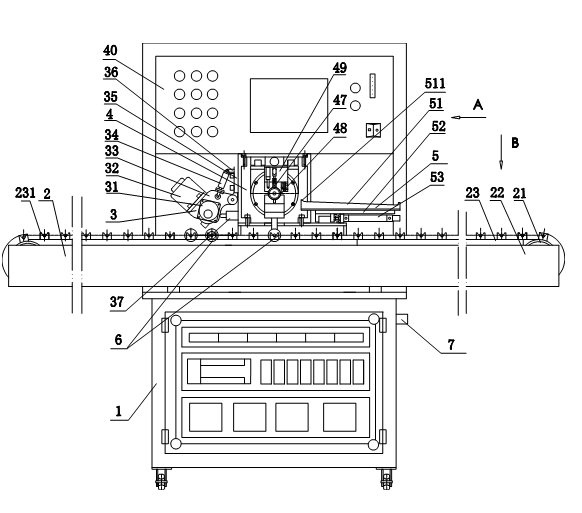
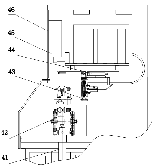
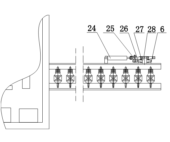
[0023] Embodiment 1: as figure 1 As shown, an automatic testing device for motor rotors with a commutator includes a machine base 1, casters are provided under the machine base, a workpiece transfer device 2 for transmitting the motor rotor and a comprehensive test bench 40 are arranged on the machine base, and the comprehensive test bench A comprehensive testing device 4 is provided on the comprehensive testing device 4, and a workpiece performance comprehensive testing instrument 45 and an electrical controller 46 including a computer system are arranged on the comprehensive testing device 4. The electrical controller is provided with a digital display device, and on one side of the comprehensive testing device 4 An automatic cleaning device 3 for the motor rotor commutator is provided, and a defective product sorting device 5 is provided on the other side of the comprehensive testing device 4. At the end of the automatic cleaning device 3, the comprehensive testing device 4 ...

Embodiment 2

[0028] Embodiment 2: The toothed ratchet device in Embodiment 1 is replaced by a ratchet device with two pawls, which can achieve the effect that the argument angle of rotation can be changed at the level of half teeth, that is, the distance that the chain can move each time can be divided into half teeth. Adjustment, this structure is beneficial to move the motor rotor to the set working position more accurately.

[0029] Dimples are arranged on the two bearing surfaces of the V-shaped seat carrying the motor rotor, rollers are arranged in the dimples, and the outer circular surface of the rollers is used to carry the motor rotor, so that the friction force of the motor rotor is small when rotating.

Embodiment 3

[0030] Embodiment 3: The toothed ratchet device in Embodiment 1 is replaced by a silent ratchet device, which can achieve the effect of stepless change in the argument of rotation, that is, the distance that the chain moves each time can be adjusted arbitrarily. This structure is conducive to making the motor The rotor moves very precisely to the set working position.

[0031] Miniature rolling bearings are arranged on the two bearing surfaces of the V-shaped seat bearing the motor rotor, and the outer circular surface of the rolling bearing is used to carry the motor rotor, so that the friction force of the motor rotor is extremely small when rotating.

[0032] On the bracket of the workpiece conveying device, a pair of infrared position sensing devices are added, and an audible and visual alarm device is provided. When the rotor of the motor passing the test is delivered to this position, an alarm can be given in advance without stopping the machine. The infrared ray The ins...


PUM


Abstract

The invention discloses an automatic testing device with a reverser motor rotor winding and provides a testing device which can be used for automatically cleaning a rotor reverser, continuously and automatically performing comprehensive testing and automatically sorting defective products. The automatic testing device is characterized in that an engine base is provided with a motor rotor conveying device and a comprehensive testing device, wherein the comprehensive testing device comprises a motor rotor performance comprehensive tester and an electric controller with a computer system; one side of the comprehensive testing device is provided with a motor rotor reverser automatic cleaning device, and the other side of the comprehensive testing device is provided with a defective product sorting device; the tail ends of the automatic cleaning device, the comprehensive testing device and the motor rotor conveying device are provided with a pair of infrared sensing devices respectively; and the engine base is provided with a pipe joint connected with a compressed air source. By adopting the automatic testing device, the surface of the reverser can be automatically cleaned completely, so that the false detection rate can be lowered; and defective products are sorted automatically after comprehensive testing, so that the motor rotor testing efficiency is greatly increased, and the labor intensity is greatly lowered.

Description

technical field [0001] The invention relates to a motor testing device, in particular to a motor rotor automatic testing device. Background technique [0002] Existing motor production requires a comprehensive test of the rotor. This test can only be performed on the rotor piece by piece. Generally, the product to be tested needs to be clamped manually, and the commutator surface of the rotor is simply cleaned manually. After the test is completed It is also necessary to use manual sorting to detect defective products. This testing process cannot be integrated with automated assembly lines, and the efficiency is low and the error is large. [0003] For example, Chinese Patent No. ZL200420110739.X, the patent titled DC Motor Rotor Comprehensive Detector, its gist is that a motor and a first cylinder are arranged oppositely on the test platform, and a magnetic field generator is arranged between the motor and the first cylinder. A third cylinder is arranged next to the motor,...

Claims


Application Information

Patent Timeline
Patent Type & Authority Applications(China)
IPC IPC(8): G01M13/00G01R31/34B08B1/00B07C5/36B07C5/34
Inventor 翁惠良
Owner NINGBO DECHANG ELECTRICAL MACHINERY MFG CO LTD
Learn More