Manufacturing method of carbon nano-tube micro-channel cooler system

A technology of carbon nanotubes and microchannels, which is applied in the direction of nanostructure manufacturing, nanotechnology, nanotechnology, etc., can solve the problems that cannot meet the heat dissipation requirements of high-density integrated circuits, and the heat dissipation performance of coolers is not high.

Inactive Publication Date: 2011-08-31
SHANGHAI UNIV
View PDF3 Cites 12 Cited by
  • Summary
  • Abstract
  • Description
  • Claims
  • Application Information

AI Technical Summary

Problems solved by technology

[0004] The present invention is aimed at the fact that the heat dissipation performance of conventional microch

Method used

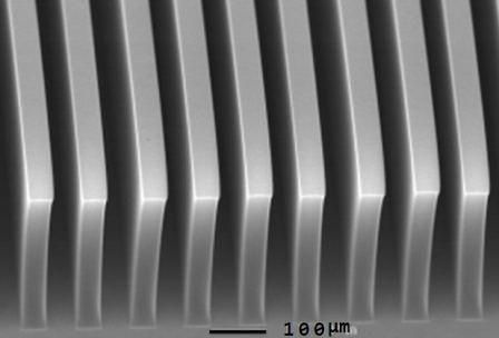
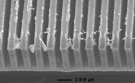
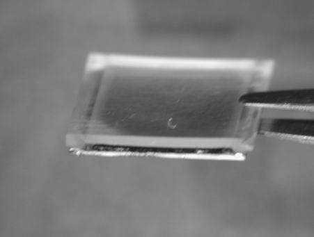

Image

  • Manufacturing method of carbon nano-tube micro-channel cooler system
  • Manufacturing method of carbon nano-tube micro-channel cooler system
  • Manufacturing method of carbon nano-tube micro-channel cooler system

Examples


Embodiment 1

[0022] In this embodiment, the method of preparing a carbon nanotonal microstructure cooler method is adopted. The specific steps are as follows:

[0023] 1 Spread a layer of peeling glue on the silicon wafer. After heating this layer of peeling glue, apply another layer of standard positive adhesive on it. After 30 seconds of exposure of ultraviolet rays, after 45 seconds of MF319, the peeling glue forms formation to form the formationThe bottom -cut structure is covered with a steam plating process on the entire surface to cover a layer of catalytic film, and then the silicon wafer will be placed in the photoresal gum removal, peeling off the catalyst film that is peeled off, light -engraved glue, and attached to the photoresal glue. In the endThe catalyst pattern that is formed on the silicon wafer to cover the same pattern as the photoresistate, and the catalyst film is composed of 10 nanometer -thick aluminum dioxide and 1 nanometer thick iron;

[0024] 2 Place the chip carry...


PUM


Abstract

The invention discloses a manufacturing method of a carbon nano-tube micro-channel cooler system for a radiating chip in a very-large scale integrated circuit (VLSI), which comprises the following steps of: firstly, manufacturing a pattern with required fine scale through a photoetching and peeling process; meanwhile, adhering a catalyst film obtained through an evaporation method on a surface ofthe pattern; secondly, placing a silicon wafer with the catalyst film in a heating furnace of a carbon nano-tube growth machine, growing in a high-temperature chemical vapor deposition mode to obtainthe required carbon nano-tube cluster; finally, transferring the carbon nano-tube cluster on a surface of a heating chip by adopting a transferring process through a metal coating sprayed on the surface of the carbon nano-tube, heating a sealing cover, then finishing the manufacturing process of the carbon nano-tube micro-channel cooler; then radiating through the cooling liquid flowing through an entry guide to finish the manufacturing of the carbon nano-tube micro-channel cooler system. The radiating performance is obviously improved and a more efficient radiating method is provided for radiating the chip in the integrated circuit.

Description

Technical field [0001] The present invention involves a carbon nanopardic micro -channel cooler system for the heat dissipation of large -scale integrated circuit chips, which belongs to the field of micro -channel heat dissipation technology. Background technique [0002] The development of high -density integrated circuits (IC) technology, while improving the IC function, also brings a challenge of high heat flow density.At present, the power of high-density IC has reached 100-400 W / CM 2 EssenceTherefore, the heat dissipation of high -power IC becomes very important. [0003] Micro -channel cooler is an emerging and efficient cooling technology for microelectronics systems.Using this technology, the micro -channel is directly produced on the back of the chip, and the heat generated by the circuit is taken away by the cooling medium flowing through the microver. [0004] The present invention is invented by the current conventional micro -channel cooler's heat dissipation perfor...

Claims


Application Information

Patent Timeline
IPC IPC(8): H01L21/48B82B3/00H01L23/473
CPCB82Y10/00H01L23/473H01L23/373H01L2924/0002H01L2924/00
Inventor 刘建影
Owner SHANGHAI UNIV
Why Eureka
Try Eureka