
Cold crucible for directional solidification of magnetic AlNiCo alloy

A magnetic alloy and directional solidification technology, applied in the field of cold crucibles, can solve problems such as low energy utilization, inability to laterally dissipate thermal compensation, discontinuous columnar crystals, etc., to improve energy utilization, optimize height, and increase transparency. magnetic effect

Inactive Publication Date: 2011-09-07
HARBIN INST OF TECH
View PDF0 Cites 9 Cited by
  • Summary
  • Abstract
  • Description
  • Claims
  • Application Information

AI Technical Summary

Problems solved by technology

[0004] The purpose of the present invention is to solve the problem that the existing cold crucible has a low energy utilization rate when directional solidifying magnetic alloys, and cannot perform thermal compensation on its lateral heat dissipation, resulting in discontinuous columnar crystals, and further provides a Cold crucible for directionally solidified AlNiCo magnetic alloy

Method used


Image

  • Cold crucible for directional solidification of magnetic AlNiCo alloy
  • Cold crucible for directional solidification of magnetic AlNiCo alloy
  • Cold crucible for directional solidification of magnetic AlNiCo alloy

Examples


specific Embodiment approach 1

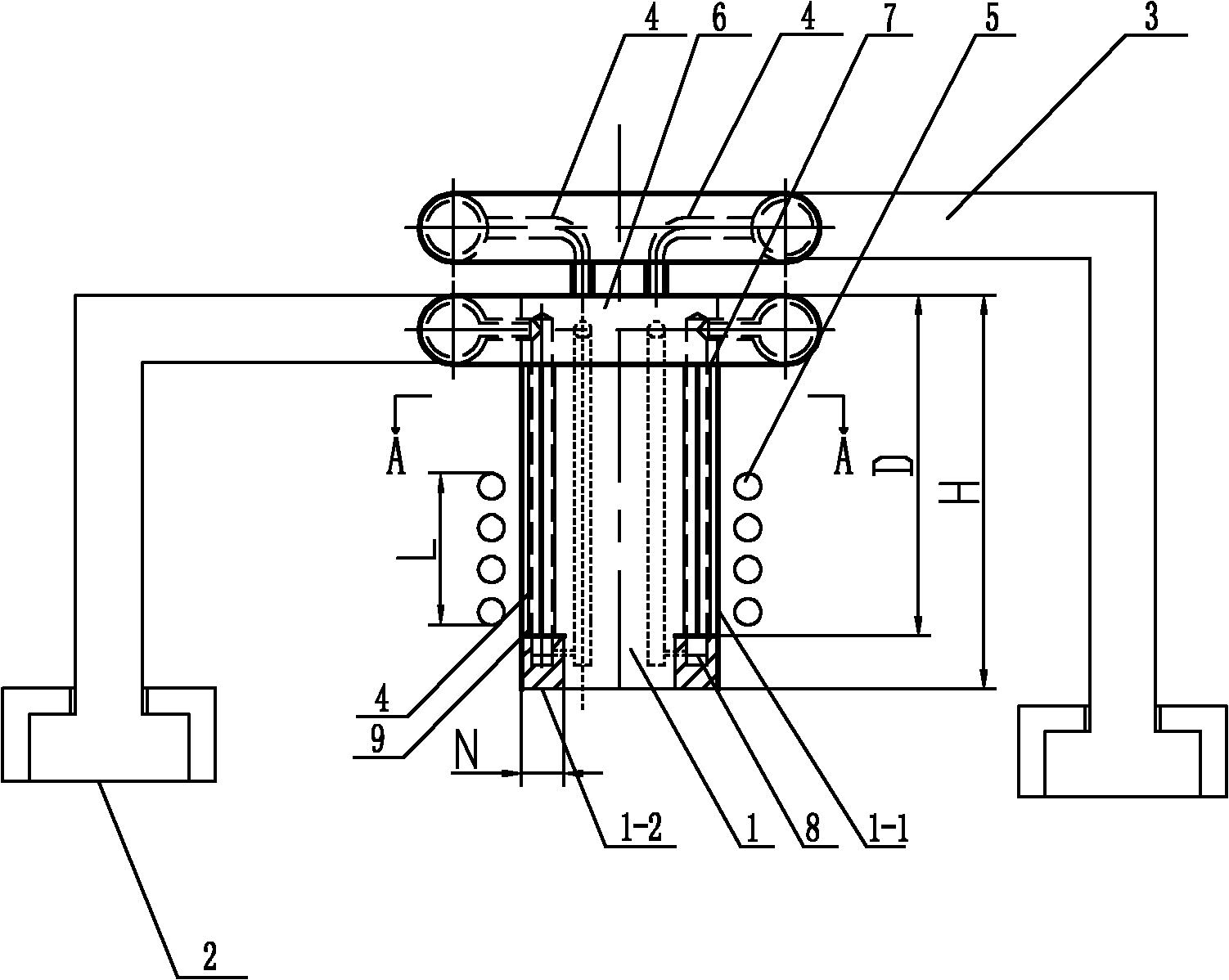
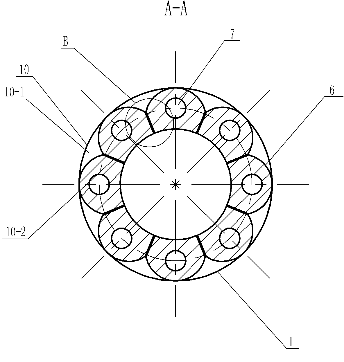
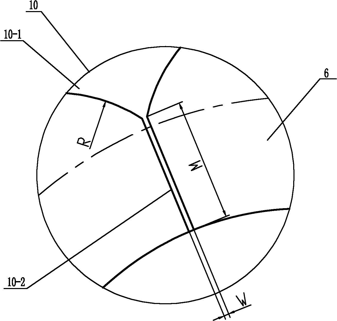
[0008] Specific implementation mode one: combine Figure 1-Figure 4 To illustrate this embodiment, a cold crucible for directionally solidified AlNiCo magnetic alloy in this embodiment includes a crucible main body 1, a water inlet pipe 2, a water outlet pipe 3, an induction coil 5 and eight cooling connecting water pipes 4, and the crucible main body 1 includes an upper The half body 1-1 and the lower half body 1-2, the upper half body 1-1 and the lower half body 1-2 are fixedly connected, the induction coil 5 is set on the upper half body 1-1, and the crucible main body 1 The cross-section is a ring-shaped hollow body, and the outer wall of the upper body 1-1 is divided into eight petal-shaped cylinders 6 with arc-shaped cross-sections, and the eight petal-shaped cylinders 6 with arc-shaped cross-sections are along the crucible The horizontal axis and the vertical axis on the horizontal section of the main body 1 are arranged symmetrically, the intersection point of the hori...

specific Embodiment approach 2

[0009] Specific implementation mode two: combination figure 1 The present embodiment will be described. The height D of the upper body 1-1 of the present embodiment is 85mm-105mm. Such setting makes the position of the solid-liquid interface of the AlNiCo magnetic alloy close to the maximum magnetic field of the coil, and at this time, the utilization rate of energy is the best. Other compositions and connections are the same as in the first embodiment.

specific Embodiment approach 3

[0010] Specific implementation mode three: combination figure 1 The present embodiment will be described. The induction coil 5 of the present embodiment is wound by a red copper wire, and the diameter of the red copper wire is 10 mm. With such setting, the conduction effect is the best. Other compositions and connections are the same as those in Embodiment 1 or Embodiment 2.

[0011] Specific implementation mode four: combination figure 1 The present embodiment will be described. The height L at which the induction coil 5 of the present embodiment is wound is 50mm-70mm. Such setting can effectively support the alloy melt of 20mm-30mm. Other compositions and connections are the same as those in the third embodiment.


PUM

PropertyMeasurementUnit
heightaaaaaaaaaa
diameteraaaaaaaaaa

Abstract

The invention discloses a cold crucible for directional solidification of magnetic AlNiCo alloy, relating to a cold crucible. The invention aims to solve the problems that when the existing cold crucible is used for directional solidification of magnetic alloy, the utilization rate of energy is low, and the side heat dissipation cannot have well thermal compensation, thereby resulting in discontinuous columnar crystals. The outer wall of the upper half of the cold crucible is divided into eight cylinders with arc petal-shaped sections, an opening seam is arranged between every two adjacent cylinders with the arc petal-shaped sections, the arc radius of each arc petal-shaped cylinder is 9 mm, the opening seam length of the opening seam is 4 mm, the opening seam width is 0.5 mm, a through hole is arranged inside each cylinder with the arc petal-shaped section, every odd number of cooling connection water pipe in eight cooling connection water pipes is communicated with a water inlet pipe, every even number of cooling connection water pipe in the eight cooling connection water pipes is communicated with a water outlet pipe, the height of the main body of the crucible is 110mm-130mm, and the wall thickness of the main body of the crucible is 12mm-15mm. The cold crucible is suitable for directional solidification of magnetic alloy.

Description

technical field [0001] The invention relates to a cold crucible, in particular to a cold crucible for directionally solidified AlNiCo magnetic alloy. Background technique [0002] The so-called directional solidification is a technical means to control the solidification or crystallization of metal or crystal materials along a fixed growth direction under the conditions of controlling heat transfer, mass transfer and flow inside the blank. The microstructure of metals after directional solidification is characterized by a group of parallel columnar grains parallel to the direction of solidification heat flow. If the growth process of grains can be properly controlled, such as inhibiting external nucleation, the crystals can grow into a crystalline structure with only one grain. called a single crystal. It can be seen that directional solidification is a special material processing technology under the basic conditions of one-way heat and mass transfer. [0003] The permane...

Claims


Application Information

Patent Timeline
Patent Type & Authority Applications(China)
IPC IPC(8): C30B21/00B22D27/00
Inventor 丁宏升王永喆陈瑞润郭景杰傅恒志
Owner HARBIN INST OF TECH
Learn More