Device and method for detecting refractive index of optical flat based on displacement sensor

A technology of displacement sensor and optical plate, applied in the field of optical measurement, to achieve the effects of simple and easy detection, simple structure and convenient detection

Inactive Publication Date: 2011-09-07
CHANGCHUN UNIV OF SCI & TECH
View PDF2 Cites 8 Cited by
  • Summary
  • Abstract
  • Description
  • Claims
  • Application Information

AI Technical Summary

Problems solved by technology

[0004] In order to overcome the problems existing in the existing automatic V-prism refractometer and V-prism method, obtain a simple structure, low-cost transparent optical material refractive index detection device, and at the same time obtain a transparent optical material with easy processing and small detection error Material refractive index detection method, we invented an optical flat plate refractive index detection device and method based on displacement sensor

Method used


Image

  • Device and method for detecting refractive index of optical flat based on displacement sensor
  • Device and method for detecting refractive index of optical flat based on displacement sensor
  • Device and method for detecting refractive index of optical flat based on displacement sensor

Examples


Embodiment Construction

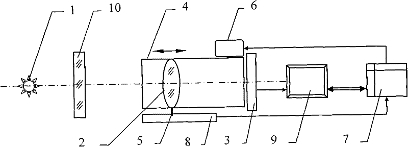
[0010] The detection device of the present invention is specifically implemented in this way, see figure 1 As shown, the light source 1, the imaging optical system 2, and the CCD image sensor 3 are optically coaxially arranged in sequence. The light source 1 adopts an LED lamp. The imaging optical system 2 is located in the cam barrel 4 and connected to the sliding pin 5 of the displacement sensor. The motor 6 drives the cam barrel 4 to rotate. The motor 6 adopts a stepping motor. The control and processing circuit 7 is electrically connected to the motor 6 and the displacement sensor 8 respectively, and is connected to the serial port of the upper computer 9. The control and processing circuit 7 uses a single-chip microcomputer. The displacement sensor 8 adopts a tie rod potentiometer with a measuring range ≤50 mm and an accuracy of micron level. The upper computer 9 uses a microcomputer. The CCD image sensor 3 is also electrically connected to the host computer 9.

[0011...


PUM

PropertyMeasurementUnit
thicknessaaaaaaaaaa
refractive indexaaaaaaaaaa

Abstract

The invention relates to a device and method for detecting the refractive index of an optical flat based on a displacement sensor, belonging to the technical field of optical measurement. When he existing automatic V-prism refractometer is adopted for detection, two vertical planes are needed to be processed on a measured piece, and the structure of the detection device is complicated. The detection device provided by the invention comprises a light source, an optical imaging system and a CCD (Charge Coupled Device) image sensor which are optically, coaxially and sequentially ranked, wherein the optical imaging system is positioned in a cam cylinder and is in slide pin connection with the displacement sensor; a motor drives the cam cylinder to rotate and controls a processing circuit to be respectively electrically connected with the motor and the displacement sensor and connected with the serial port of an upper computer; and the CCD image sensor is also electrically connected with the upper computer. The detection method provided by the invention comprises the following steps: processing a material to be detected into the measured piece of the optical flat; clearly imaging the infinite distance through the optical imaging system; clearly imaging a close object point A and obtaining the displacement delta S1' of the main surface H of the optical imaging system; adding the measured piece of the optical flat and clearly imaging the refractive image A' of the measured piece of the optical flat in the close object point A to obtain the displacement delta S2'; and computing the refractive index n of the material to be detected according to the displacement delta S1' and the displacement delta S2'.

Description

Technical field [0001] The invention relates to a displacement sensor-based optical flat refractive index detection device and method, and belongs to the technical field of optical measurement. Background technique [0002] The accurate detection of the refractive index of transparent optical materials is a prerequisite for improving the quality of optical instruments. The existing method for detecting the refractive index of optical materials is the V prism method, and the device used is an automatic V prism refractometer. For example, a Chinese invention patent with application number 90102943.2 discloses an automatic V prism refractometer. Light source, condenser, filter, slit, beam splitter, collimating objective lens, V prism, collimating mirror, moiré grating disc, angle encoder, variable speed vibration slit, photomultiplier tube, drive system, control circuit , Signal processing system and computer. The refractometer obtains the refractive index by detecting the deflecti...

Claims


Application Information

Patent Timeline
Patent Type & Authority Applications(China)
IPC IPC(8): G01N21/41
Inventor 向阳丁红昌刘波刘畅初宏亮席娅娜程远
Owner CHANGCHUN UNIV OF SCI & TECH
Why Eureka
Try Eureka