Photoacoustic elastic imaging method and device

A technology of photoacoustic elasticity and imaging method, which is applied in the generation of ultrasonic/sonic wave/infrasonic wave, etc., can solve limitations and other problems, achieve the effect of reducing intensity attenuation and wide application

Active Publication Date: 2011-09-07
SOUTH CHINA NORMAL UNIVERSITY
View PDF3 Cites 28 Cited by
  • Summary
  • Abstract
  • Description
  • Claims
  • Application Information

AI Technical Summary

Problems solved by technology

Because this method requires specific processing of the sample, it has significant limitations in imaging elastic information of tissues

Method used


Image

  • Photoacoustic elastic imaging method and device
  • Photoacoustic elastic imaging method and device
  • Photoacoustic elastic imaging method and device

Examples


Embodiment 1

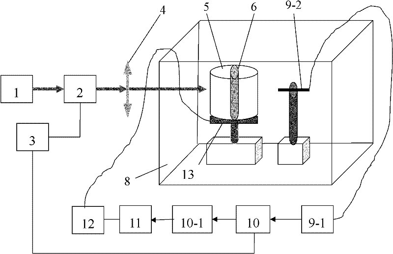
[0040] The components of this device are selected as follows: the continuous laser 1 is a domestic semiconductor laser that can emit continuous laser light with a wavelength of 808nm; the electro-optic modulator 2 is a product of Conoptics in the United States, the model is M-360; the function generator is a product of Tektronix. , its output signal is set as a sinusoidal waveform signal with a frequency of 50Khz; the acquisition control program is realized by LABVIEW software, and the image reconstruction program is realized by matlab software; the computer 11 can be a P4 microcomputer, and the internal memory is more than 128M; the sample pool 8 is made of plexiglass The cuboid box of making, is filled with water in the sample pool 8, and its inner wall is coated with sound-absorbing material; It is formed by cooling and condensing. The sample 6 to be tested is that materials with different elasticity such as metal, plastic, tape, soap, etc. are placed in the same plane, and ...

Embodiment 2

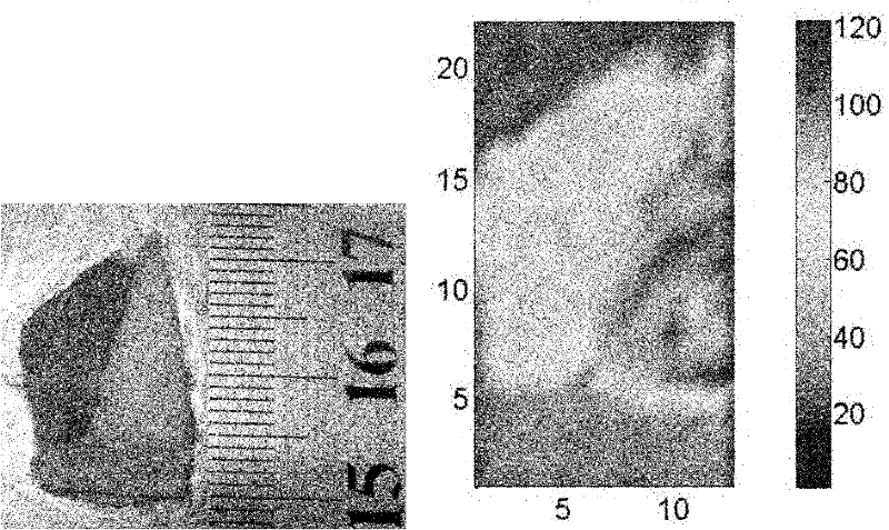
[0042] A piece of animal muscle, a piece of animal fat, and a piece of animal bone tissue with different elasticity are placed in the same plane to form the sample 6 to be tested, and the sample is fixed with agar 5. The specific shape is as follows: image 3 as shown in a. Then the computer drives the stepper motor 13 through the control circuit 12 to move the sample point by point, and realizes point by point scanning of the sample. At the same time, the unit probe receives the photoacoustic signal in real time, and the lock-in amplifier 10 detects the frequency and calculates the phase difference, and the computer 11 stores each Point phase difference value and coordinates, and correspond them one by one. The scanning step is 1mm. The collected data was reconstructed using MATLAB software (such as image 3 shown in b). From the experimental results, it can be seen that the method and device of the present invention can reconstruct the photoacoustic image of the elastic d...


PUM

PropertyMeasurementUnit
wavelengthaaaaaaaaaa

Abstract

The invention discloses a photoacoustic elastic imaging method, wherein the photoacoustic elastic imaging method comprises the following steps: exciting and generating a photoinduced thermal elastic ultrasound signal by an intensity modulated continuous light source, and reconstructing an elastic distribution image of a sample to be detected via measuring the phase difference between the signal and a modulation signal and scanning point by point. The invention further discloses a photoacoustic elastic imaging device, wherein the photoacoustic elastic imaging device comprises a photoacoustic excitation light source generating assembly, a photoacoustic signal collecting assembly and a photoacoustic signal processing assembly; and the photoacoustic excitation light source generating assembly, the photoacoustic signal collecting assembly and the photoacoustic signal processing assembly are electrically connected in sequence. In the invention, the detects such as the traditional elastic imaging method is influenced by the tissues around the area to be detected, and the like are overcome; the images reflecting the tissue elastic distribution with new principle can be provided; the location is accurate; and the resolution ratio is high. The device disclosed by the invention is low in cost, and is easy to be popularized.

Description

technical field [0001] The invention relates to an elastic imaging technology, in particular to a photoacoustic elastic imaging method and a device thereof. Background technique [0002] Elasticity is an important parameter to characterize the physical properties of a substance. Measuring the elasticity of a certain substance or imaging its distribution of elastic properties is a very important means for understanding the properties and structure of the substance. As a new imaging method, elastography makes up for the shortcomings of traditional imaging modalities such as X-ray, ultrasound imaging (US), magnetic resonance imaging (MRI), and computed tomography (CT) by obtaining information about tissue elasticity. The lack of tissue elasticity is provided directly. [0003] The word elastography originally comes from static / quasi-static compression ultrasound elastography. In a narrow sense, elastography refers only to this imaging method. The basic principle is to apply an...

Claims


Application Information

Patent Timeline
Patent Type & Authority Applications(China)
IPC IPC(8): G01N29/34
Inventor 邢达高国栋杨思华
Owner SOUTH CHINA NORMAL UNIVERSITY
Why Eureka
Try Eureka