
Matched filtering method

A matched filter and matched filter technology, applied in the field of matched filter, to achieve the effect of reducing requirements and difficulty

Inactive Publication Date: 2011-09-07
TSINGHUA UNIV
View PDF2 Cites 3 Cited by
  • Summary
  • Abstract
  • Description
  • Claims
  • Application Information

AI Technical Summary

Problems solved by technology

[0015] The technical problem to be solved by the present invention is how to reduce the computational complexity of matched filtering so as to reduce the difficulty of hardware implementation. Another technical problem to be solved by the present invention is how to meet the transmission requirements of the high-speed digital transmission system

Method used


Image

  • Matched filtering method
  • Matched filtering method
  • Matched filtering method

Examples


Embodiment

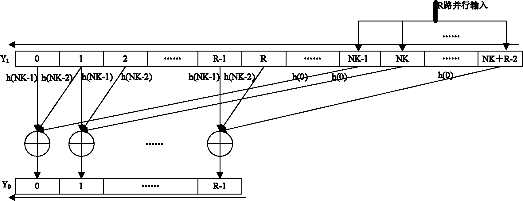
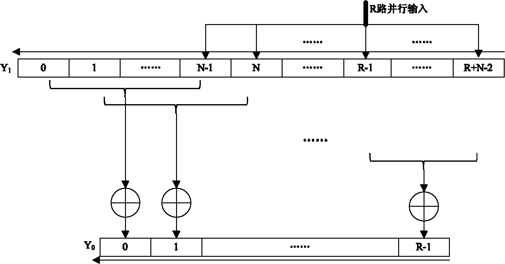
[0042] The shaping filter at the sending end is an RRC root raised cosine filter, parameter α=1, the filter impulse response is 6 symbol periods, and the system upsampling multiple is 4, so the order of the shaping filter is 24. According to the design principle, the order of the square wave matched filter should be 4 or 5, and the impulse response should be [1 / 2 1 / 2 1 / 2 1 / 2] or If the selected order is 4, and each time 8 channels are processed in parallel, the matching filtering implementation is shown in 4.

[0043] Such as Figure 4 As shown, the required arithmetic units are only eight 4-input adders, and the circuit implementation structure is relatively simple. Since the filter coefficients are all 1 / 2, it will only affect the overall amplitude and will not change the waveform. For performance evaluation, a design such as Figure 5In the MATLAB simulation platform shown, the matched filter uses root-raised cosine matching and square wave matching for comparison, and t...


PUM


Abstract

The invention discloses a matched filtering method in which a square wave is used as a swash response of a matched filter, and various filtering coefficients are fixed values. In the invention, the square wave is used as the swash response of the matched filter, and the filtering coefficients are fixed values, thus floating point multiplication required when the traditional matched filter selects an image of a selective forming filter can be avoided, and summation and accumulation of various items are just needed, thereby decreasing achievement difficulty of hardware; the length of the swash response of the matched filter is designed to be a sign period, if the multiple of the sampling is N, order of the filter is N or N+1 which is far smaller than the NK (K is the lasting sign period number of the swash response of the forming filter) of the traditional matched filter, thereby further reducing the achievement requirement of the hardness; and R paths are selected to carry out parallel treatment, so that the work rate of the matched filter is 1 / R less than the transmission rate of data, thereby further meeting the transmission requirement of a high-speed data system.

Description

technical field [0001] The invention relates to the field of digital communication, in particular to a matched filtering method. Background technique [0002] In a digital communication system, in order to save transmission bandwidth and enable the receiving end to sample and restore the analog signal according to the Nyquist sampling criterion, the sending end usually needs to low-pass filter the digital signal to realize waveform shaping. At the receiving end, the analog signal is first sampled at N times the symbol rate. In order to maximize the signal-to-noise ratio of the signal at the sampling moment, the signal needs to be matched and filtered. The most effective matched filter is the mirror image of the shaping filter at the sending end. Causality also requires a certain delay. After matched filtering, sampling is performed at the time when the signal-to-noise ratio of each corresponding symbol is maximum, that is, down-sampling by N times to generate symbol rate le...

Claims


Application Information

Patent Timeline
IPC IPC(8): H03H11/30
Inventor 张昌明肖振宇高波金德鹏苏厉曾烈光
Owner TSINGHUA UNIV
Learn More