Magnetorheological vibration reduction system based on shearing work mode for cylindrical turning vibrations

A technology of external turning and shearing work, applied in turning equipment, manufacturing tools, accessories of toolholders, etc., can solve the problems of turning chatter in machining volume, reduce turning noise, suppress chattering in external turning, extend The effect of tool life

Inactive Publication Date: 2011-09-14
UNIV OF SHANGHAI FOR SCI & TECH
View PDF5 Cites 12 Cited by
  • Summary
  • Abstract
  • Description
  • Claims
  • Application Information

AI Technical Summary

Problems solved by technology

In 2006, Mei Deqing of Zhejiang University and others applied for an invention patent that introduced the magnetorheological effect into boring processing, and developed a self-suppressing vibration intelligent boring bar system based on magnetorheological fluid; for turning processing, in 2007, Xu Ping et al. Metal foam is added to the conventional magnetorheological fluid to develop a magnetorheological-foam metal damper that can be used to suppress chatter during cutting and turning. However, for the slender shaft that has a large amount of processing and is prone to chatter external turning chatter of such parts, the damper is powerless

Method used


Image

  • Magnetorheological vibration reduction system based on shearing work mode for cylindrical turning vibrations
  • Magnetorheological vibration reduction system based on shearing work mode for cylindrical turning vibrations
  • Magnetorheological vibration reduction system based on shearing work mode for cylindrical turning vibrations

Examples


Embodiment Construction

[0018] The present invention will be further described below in conjunction with the accompanying drawings and embodiments.

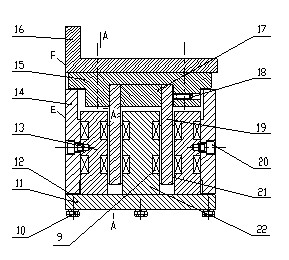
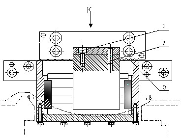
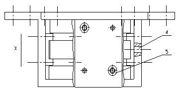
[0019] Figure 1 to Figure 4 As shown, the present invention is composed of two major parts, a sliding pole assembly and a fixed pole assembly, wherein the sliding pole assembly mainly includes parts such as an upper limit slot 15, a connecting plate 16, an upper separator 17, and an upper magnetic pole 19, and the entire sliding pole assembly passes through The connecting plate 16 is fixed on the lathe horizontal carriage with screws; and the fixed magnetic pole assembly mainly includes parts such as the lower limit groove 7, the lower magnetic poles 13 on two sides, the lower magnetic pole 22 in the middle, the lower bottom plate 11 and the lower box body 14, and it passes through Lower casing 14 is fixed on the saddle side plane with screws. During the vibration process of outer circle turning, the vibration of the turning tool will be transmitted t...


PUM


Abstract

The invention relates to a magnetorheological vibration reduction system based on a shearing work mode for cylindrical turning vibrations. An upper spacing groove is adjustably connected below a connecting plate inside a sliding magnetic pole assembly; two upper magnetic poles are fixedly connected below the upper spacing groove through upper partition plates; a lower spacing groove inside a fixed magnetic pole assembly is fixedly connected with a lower box body in a positioning way; the lower spacing groove is internally connected with a middle lower magnetic pole in an interference fit way;the inner side surface of the box body is fixedly connected with two side lower magnetic poles; magnet exciting coils are transversely wound in square grooves positioned on the outer surfaces of the side lower magnetic poles and the middle lower magnetic pole, and magnetorheological fluids are injected between the upper magnetic poles and the lower magnetic poles; an acceleration transducer is arranged on the front end of a lathe cross slide and sequentially connected with a charge amplifier, a computer and a program-controlled DC power supply through cables; and the program-controlled DC power supply is connected with the magnet exciting coils. The magnetorheological vibration reduction system has important application values to effectively enhancing the processing quality and the production efficiency of cylindrical turning, especially the cylindrical turning of slender axle parts, prolonging the lives of cutters and reducing turning noises.

Description

technical field [0001] The invention relates to a vibration damping system for turning, in particular to a magneto-rheological vibration damping system for outer circle turning. Background technique [0002] Cutting chatter is a dynamic instability phenomenon in the closed-loop cutting system of machine tools. It occurs between the cutting tool and the workpiece, and is an important factor restricting the improvement of the processing level of modern manufacturing. In turning processing, chattering is easy to occur when turning shaft parts with relatively large length and diameter, such as crankshafts and camshafts in engines, etc. How to improve the processing quality and production efficiency of such parts and reduce the processing time The flutter that appears in the machine has become one of the important issues to be solved urgently in the machinery manufacturing industry. [0003] According to the chatter prevention theory, adding a vibration damping device in the mac...

Claims


Application Information

Patent Timeline
Patent Type & Authority Applications(China)
IPC IPC(8): B23B25/00F16F9/53
Inventor 张永亮周渊刘军
Owner UNIV OF SHANGHAI FOR SCI & TECH
Why Eureka
Try Eureka