Pressure limiting seal piston and exhaust brake butterfly valve thereof

A sealing piston, exhaust braking technology, applied in the directions of pistons, brakes, brake components, etc., can solve the problems of unstable air pressure, easy resonance, increased noise, etc., to achieve a simple and compact structure, reduce exhaust gas leakage, reduce The effect of small movement resistance

Inactive Publication Date: 2011-09-14
ZHEJIANG EASUN PNEUMATIC SCI & TECH
View PDF4 Cites 12 Cited by
  • Summary
  • Abstract
  • Description
  • Claims
  • Application Information

AI Technical Summary

Problems solved by technology

Since the existing tappet adopts an equal-diameter structure, it is not easy to control its position and movement stroke
At the same time, under the action of air flow, the tappet is easy to be attached to the side wall of the tappet hole due to the Coanda effect, resulting in a large amount of gas leakage and affecting the braking effect.
In addition, since the top of the tappet protrudes inside the valve body, the spring installed in the inner cavity of the tappet works in the high-temperature environment of the engine exhaust in the valve inner cavity, and it is very easy to fail due to thermal deformation.
Have again, in order to ensure that the existing exhaust brake valve reaches a good braking effect, the rigidity of the spring that is required to be arranged in the inner cavity of the tappet is relatively large, and its rigidity is similar to the valve spring rigidity of the engine. , the two are prone to resonance, increased noise, and even bring safety hazards
Moreover, there are usually multiple cylinders in the engine, and different cylinders perform work in the order of suction, pressure, explosion, and discharge. The engine exhaust gas in the intake chamber of the valve body enters in a pulsating manner, and the air pressure is unstable.

Method used


Image

  • Pressure limiting seal piston and exhaust brake butterfly valve thereof
  • Pressure limiting seal piston and exhaust brake butterfly valve thereof
  • Pressure limiting seal piston and exhaust brake butterfly valve thereof

Examples


Embodiment 1

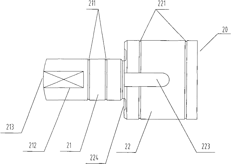
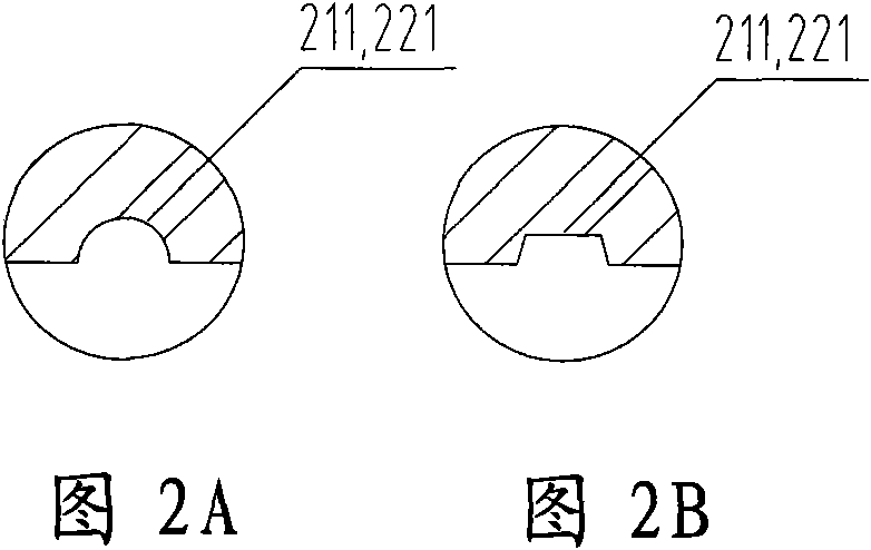
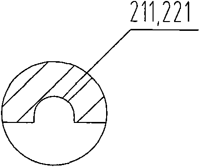
[0042] figure 1 It is a schematic structural diagram of Embodiment 1 of the pressure-limiting sealing piston of the present invention. like figure 1As shown, the present invention provides a pressure-limiting sealing piston 20, including a piston body, the piston body is stepped, and consists of an upper tappet 21 and a lower support 22, the diameter of the tappet 21 is smaller than that of the support 22 A first ring groove 211 is opened on the outer surface of the tappet 21 . According to different needs, the number of the first annular grooves 211 may be one or more than one. When the number of openings is more than one, the interval between two adjacent first annular grooves 211 should not be less than 2 mm. At the same time, a second annular groove 221 is opened on the outer surface of the support 22 . The number of the second ring grooves 221 can also be one or more. When the number of the second ring grooves 221 is more than one, in order to ensure the sealing prope...

Embodiment 2

[0058] In the above-mentioned first embodiment, when the pressure-limiting device of the butterfly valve adopts the structure of a pressure-limiting spring 7, in order to ensure that the pressure-limiting spring 7 is not bent due to the force in its interior, thereby affecting the accuracy of the butterfly valve's setting of the limiting pressure, A spring mounting hole 222 is provided at the rear of the support 22 of the pressure-limiting sealing piston, see image 3 , Figure 4 As shown, the outer diameter of the spring mounting hole 222 is used to locate the compression limiting spring 7, the mounting hole should be designed as a blind hole, and the depth of the blind hole is required to be greater than or equal to twice that of the compression limiting spring 7 in the pre-stressed state. lead, so as to ensure that the pressure-limiting spring 7 is not likely to come out after being stressed.

[0059] Figure 13 It is a sectional view of the second embodiment of the press...


PUM


Abstract

The invention relates to a pressure limiting seal piston which comprises a step-shaped piston body, wherein the step-shaped piston body comprises a tappet rod (21) and a support seat (22); a first annular groove (211) is arranged on the outer surface of the tappet rod (21); the pressure limiting seal piston (20) is slidably installed in a pressure limiting device shell (8) on the side wall of a valve body (1) of an exhaust brake butterfly valve; the tappet rod (21) convexly extends to an inner cavity of the valve body (1) by a through hole (100) arranged in the inner wall of the valve body (1) and is correspondingly inserted into a pressure relief notch (31); the support seat (22) is arranged on the pressure limiting device shell (8); static pressure holes (9) are also arranged outside the through hole (100) and in the air inlet cavity wall; the first annular groove (211) is positioned inside the through hole in the inner wall of the valve body; the bottom of the support seat (22) is provided with a pressure limiting spring (7); and the pressure limiting spring (7) is butted against a spring end cover (40). The invention has the advantages of simple and compact structure, less pressure limiting seal piston motion resistance, less waste gas leakage and capability of effectively controlling the position and the motion stroke of the piston.

Description

technical field [0001] The invention relates to a pressure-limiting sealing piston and an exhaust brake disc valve thereof, belonging to the technical field of machinery manufacturing. Background technique [0002] The exhaust brake is an auxiliary braking device for the vehicle, especially suitable for (heavy) trucks and (large) passenger cars and engineering vehicles, which can enhance the braking performance of the vehicle without using or less use of the main brake (traditional friction). Brake), the vehicle can be controlled within a certain safe speed range, preventing vehicle braking failure and ensuring driving safety. [0003] The existing exhaust brake is mainly composed of a cylinder or a vacuum booster cylinder and an exhaust brake valve connected to it. In the normal driving state of the vehicle, the exhaust gas of the engine flows through the exhaust brake valve and is discharged. When braking is required, the vehicle's control system controls the movement of...

Claims


Application Information

Patent Timeline
Patent Type & Authority Applications(China)
IPC IPC(8): F02D9/10F02D9/06F16J1/00B60T15/02
CPCF02D9/06
Inventor 吴科峰
Owner ZHEJIANG EASUN PNEUMATIC SCI & TECH
Why Eureka
Try Eureka