Optical path structure of cylindrical anastigmatic grating dispersion type imaging spectrometer

An imaging spectrometer and spectrometer technology, applied in the field of spectrometers, can solve problems such as unrealizable, high spectral resolution and imaging resolution, and large aberration

Active Publication Date: 2011-09-14
BEIJING INSTITUTE OF TECHNOLOGYGY
View PDF9 Cites 24 Cited by
  • Summary
  • Abstract
  • Description
  • Claims
  • Application Information

AI Technical Summary

Problems solved by technology

The aberration of this type of structure is large, and it is impo

Method used


Image

  • Optical path structure of cylindrical anastigmatic grating dispersion type imaging spectrometer
  • Optical path structure of cylindrical anastigmatic grating dispersion type imaging spectrometer
  • Optical path structure of cylindrical anastigmatic grating dispersion type imaging spectrometer

Examples


Embodiment Construction

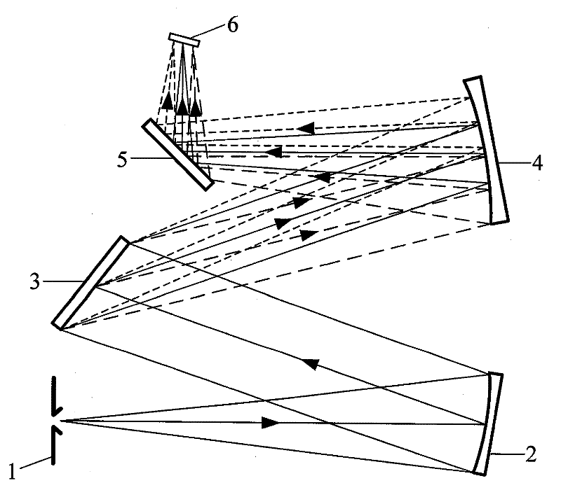
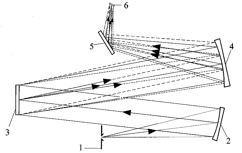
[0024] In the following, preferred embodiments according to the present invention will be described in detail with reference to the accompanying drawings. Figure 4 Shown is a schematic diagram of the optical path structure of the scanning imaging spectrometer according to the embodiment of the present invention. The optical system of the spectrometer includes a) slit 1, b) collimating objective lens 2, c) plane grating 3, d) imaging objective lens group 4, 5, e) detector 6.

[0025] The observed object is placed at the slit 1 or the real image of the observed object is at the slit 1. The light emitted by the object or the real image of the object passes through the slit 1 and is collimated and reflected by the collimating objective lens 2 to the plane grating 3 for light splitting, and then The image is focused on the photosensitive surface of the detector 6 by the focusing objective lens group 4 and 5 .

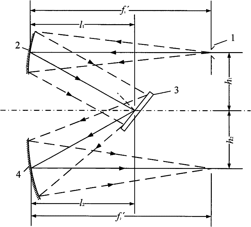
[0026] Depend on figure 2 It can be seen that the traditional Czern...


PUM

PropertyMeasurementUnit
Clear apertureaaaaaaaaaa

Abstract

The invention discloses an optical path structure of a cylindrical anastigmatic grating dispersion type imaging spectrometer. The optical structure comprises a slit (1), a collimating objective lens (2) for reflecting light passing through the slit to a grating (3), and the grating (3) for splitting the light; an imaging objective lens group consists of a spherical reflector (4) and a cylindrical reflector (5); and the split light is imaged to a photosensitive surface of a detector (6) to perform sub-spectral imaging. The spectrometer uses fully reflective optical elements, and all the reflecting elements are plated with high-reflectivity membranes. The structure is characterized by introducing a cylindrical mirror to reduce sagittal surface astigmatism of the grating dispersion type imaging spectrometer, so the spectral resolution and the imaging resolution of the spectrometer are greatly improved.

Description

technical field [0001] The invention relates to a spectrometer, in particular to an optical path structure of a grating dispersion imaging spectrometer. Background technique [0002] Imaging spectroscopy technology originated from multispectral remote sensing technology in the early 1970s, and developed with the needs of earth observation applications. It is an emerging field that combines imaging technology and spectroscopy technology. The imager obtains the image information of the target, pursues high-definition and studies its spatial characteristics; the spectrometer separates the radiation of the target into spectral radiation of different wavelengths, pursues high spectral resolution, and then measures and analyzes the target. The crystallization of the fusion of these two technologies-imaging spectrometer can obtain hyperspectral images of specific bands of the target to be measured, and has the advantage of integrating the spectrum. [0003] Dispersion-type imaging...

Claims


Application Information

Patent Timeline
IPC IPC(8): G01J3/44G01J3/02
Inventor 唐义刘健鹏吴雁张止戈倪国强
Owner BEIJING INSTITUTE OF TECHNOLOGYGY
Why Eureka
Try Eureka