Optical fiber holographic interference measuring device

A technology of holographic interferometry and measurement device, which is applied in the direction of phase influence characteristic measurement, etc. It can solve the problems of complex scanning control mechanism, laborious and laborious, and slow measurement speed, and achieve the effects of simple overall structure design, cost reduction, and easy operation

Inactive Publication Date: 2011-09-14
SHANGHAI UNIV
View PDF3 Cites 14 Cited by
  • Summary
  • Abstract
  • Description
  • Claims
  • Application Information

AI Technical Summary

Problems solved by technology

At present, the detection methods of optical fiber refractive index distribution mainly include: (1) Refractive near-field method, which analyzes the optical fiber refractive index distribution by measuring the intensity of refracted light leaked from the optical fiber. Although the resolution is high and the method is reliable, it must be detected. Cutting the optical fiber requires a high-quality cutting surface, and the required scanning control mechanism is complex and the measurement speed is slow; (2) the atomic force etching method restores the refractive index of each point by measuring the three-dimensional shape of the end face of the optical fiber, but due to the use of atomic force microscopy , leading to expensive equipment, high environmental requirements, and slow measurement speed; (3) Focusing method, which calculates the refractive index distribution by measuring the power distribution of the light after the fiber core is focused, but has relatively high requirements for the uniformity and stability of the light source illumination. High, which seriously limits the application of this method; (4) Interferometry, mainly including slice interference and transverse interference, the former puts the fiber end face slice into the interference system as a phase object, but the slice production is cumbersome, and the unevenness of the end face will be serious Affect the measurement accuracy, and the latter is to directly put the optical fiber perpendicular to the detection light into the interference system, but the adjustment of the optical path composed of various optical components is complicated, laborious, and requires high stability of the platform

Method used


Image

  • Optical fiber holographic interference measuring device
  • Optical fiber holographic interference measuring device
  • Optical fiber holographic interference measuring device

Examples


Embodiment 1

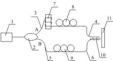
[0023] see figure 1 , a fiber holographic interferometry device, including a tunable laser light source (1), a single-mode fiber coupler (2), a piezoelectric ceramic cylinder (7), a first polarization controller (8), a second Two polarization controllers (9) and an image acquisition module (11), the tunable laser light source (1) is connected to the input end of the single-mode fiber coupler (2), and the two ends of the single-mode fiber coupler (2) The two output terminals (A, B) are respectively connected to the piezoelectric ceramic cylinder (7), the first polarization controller (8) and the second optical fiber (4) through the first optical fiber (3) to form a holographic interference reference arm, and the third optical fiber (5) Connect the second polarization controller (9), the fourth optical fiber (6) and the special optical fiber (10) in sequence to form a holographic interference signal arm, and the output light waves of the second optical fiber (4) and the special ...

Embodiment 2

[0028] This embodiment is the same as Embodiment 1, and the special features are as follows:

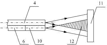
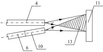
[0029] see figure 2 with image 3 ,

[0030] The interference fringe phase difference and visibility of the on-axis holographic interference area (12) and the off-axis holographic interference area (13) are determined by the deformation of the piezoelectric ceramic cylinder (7) and the first polarization controller (8) or controlled by the second polarization controller (9).

[0031] The range of the off-axis holographic interference area (13) is controlled by the angle between the second optical fiber (4) and the special optical fiber (10).

[0032] The operation method of this test device is as follows:

[0033] see figure 1 , figure 2 with image 3 .

[0034] The light emitted by the tunable laser light source (1) is divided into two beams through a single-mode fiber coupler (2), one beam of reference light and one beam of signal light, and its output wavelength is 1550 ...


PUM

PropertyMeasurementUnit
wavelengthaaaaaaaaaa

Abstract

The invention discloses an optical fiber holographic interference measuring device. The optical fiber holographic interference measuring device comprises a tunable laser source, a single mode optical fiber coupler, a piezoelectric ceramic cylinder a first polarization controller, a second polarization controller and an image acquisition module, wherein the tunable laser source is connected with an input end of the single mode optical fiber coupler; two output terminals of the single mode optical fiber coupler are respectively and orderly connected with the piezoelectric ceramic cylinder, the first polarization controller and a second optical fiber through a first optical fiber to form a holographic interference reference arm, and are orderly connected with the second polarization controller, a fourth optical fiber and a special optical fiber through a third optical fiber to form a holographic interference signal arm; and output optical waves of the second optical fiber and the special optical fiber are overlaid to form a coaxial holographic interference region or an off-axis holographic interference region, and the formed region received by the image acquisition module. The optical fiber holographic interference measuring device is high in reliability and accuracy and easy to operate, and not only can be used for measuring refraction index profile of the special optical fiber, but also can be used for measuring different types of special optical fibers, phase difference change of holographic interference fringes and outer and inner defects and damages of the special optical fibers.

Description

technical field [0001] The invention relates to an optical fiber holographic interference measurement device, which belongs to the field of photoelectric detection. Background technique [0002] In recent years, with the vigorous development of research on optical fiber communication and sensing system technology at home and abroad, the performance of optical fiber has become a key issue related to the success or failure of the system. Existing optical fiber performance testing mainly includes destructive testing (end surface three-dimensional shape measurement and fiber exit energy distribution testing, etc.) effect. Among these detection technologies, the biggest feature of the former is that the optical fiber must be cut, and the quality of the cut surface is very high; the optical path of the latter experimental device is complicated, and the adjustment accuracy of the optical path is high. In addition, if the measurement of optical fiber performance is inaccurate, res...

Claims


Application Information

Patent Timeline
Patent Type & Authority Applications(China)
IPC IPC(8): G01N21/45
Inventor 黄素娟付兴虎王廷云
Owner SHANGHAI UNIV
Why Eureka
Try Eureka