Novel cam shaft machining process
A processing technology and camshaft technology, which is applied in the field of new camshaft processing technology, can solve the problems of the full-length surface roughness of the camshaft, the flange end face bolt mounting hole position degree can not meet the requirements, the processing efficiency and processing accuracy are low, etc. Achieve the effect of improving machining accuracy, ensuring verticality, and ensuring full-length dimensions
- Summary
- Abstract
- Description
- Claims
- Application Information
AI Technical Summary
Problems solved by technology
Method used
Image

Examples
Embodiment Construction
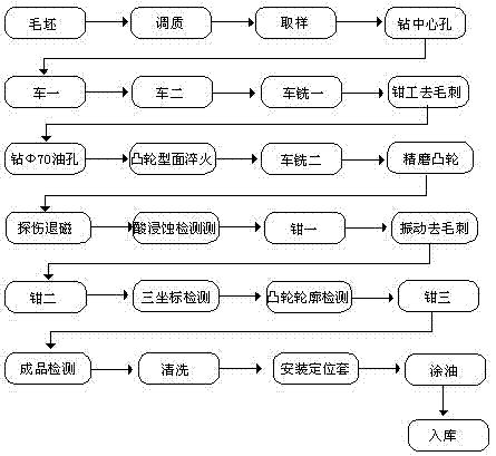
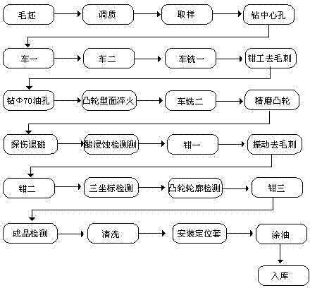
[0012] figure 1 It is a structural representation of the present invention. The figure includes blank→quenching and tempering→sampling→drilling center hole→car 1→car 2→turning and milling→fitter deburring→drilling Φ70 oil hole→cam surface quenching→turning and milling 2→finishing cam→flaw detection and demagnetization→acid Erosion inspection→clamp 1→vibration deburring→clamp 2→three-coordinate inspection→cam profile inspection→clamp 3→finished product inspection→cleaning→locating sleeve installation→oiling→storage. First, the cam profile of the blank is quenched and tempered, and then samples are taken, and the center hole is drilled through turning one and turning two. The bolt mounting holes on the flange end face of the camshaft are processed by turning and milling, which is processed by turning and milling. The measurement process determines the positioning pin hole and the bolt installation hole of the transmission phase angle of each camshaft at the two ends. The machin...
PUM
 Abstract
Description
Claims
Application Information
 - Generate Ideas
- Intellectual Property
- Life Sciences
- Materials
- Tech Scout
- Unparalleled Data Quality
- Higher Quality Content
- 60% Fewer Hallucinations
Browse by: Latest US Patents, China's latest patents, Technical Efficacy Thesaurus, Application Domain, Technology Topic, Popular Technical Reports.
© 2025 PatSnap. All rights reserved.Legal|Privacy policy|Modern Slavery Act Transparency Statement|Sitemap|About US| Contact US: help@patsnap.com