Method for extracting oil vapor from gases of dry distillation furnace

A dry distillation furnace and oil vapor technology, which is applied in the field of oil vapor extraction, can solve the problems of high energy consumption and large processing capacity, and achieve the effects of simplifying the processing process, reducing operating costs, and saving resources

Active Publication Date: 2015-03-18
SHANDONG PROVINCE METALLURGICAL ENG CO LTD
View PDF6 Cites 0 Cited by
  • Summary
  • Abstract
  • Description
  • Claims
  • Application Information

AI Technical Summary

Problems solved by technology

[0005] 2. In the process of separating shale oil, the furnace gas must be cooled together, so the energy consumption is high; at the same time, due to the relatively large processing capacity, the problem of high energy consumption is intensified

Method used


Image

  • Method for extracting oil vapor from gases of dry distillation furnace
  • Method for extracting oil vapor from gases of dry distillation furnace
  • Method for extracting oil vapor from gases of dry distillation furnace

Examples


Embodiment 1

[0033] Example 1, such as figure 1 , figure 2 , image 3 , Figure 4 shown.

[0034] figure 1 What is shown is a schematic layout diagram of the general structure of an annular movable grate retort for extracting shale oil and gas from oil shale. Wherein, 1 is the upper cover of this dry distillation furnace. 2 is the moving grate of this carbonization furnace, and this moving grate rotates around center line 5. 3 is the oil shale laid on the movable grate 2. 4 is the lower cover of this dry distillation furnace. The heat-carrying gas or furnace gas enters through the intake pipe 6 , passes through the shale oil layer and is discharged through the exhaust pipe 7 . Its sealing task is finished by closing casing 8.

[0035] In this embodiment, oil vapor absorption tanks 9 and 10 are provided, which are all directly connected to the dry distillation furnace, and these tanks can also be arranged in multiple points. Since their functions are interlinked, only the absor...

Embodiment 2

[0045] Example 2, such as Figure 5 , Image 6 shown.

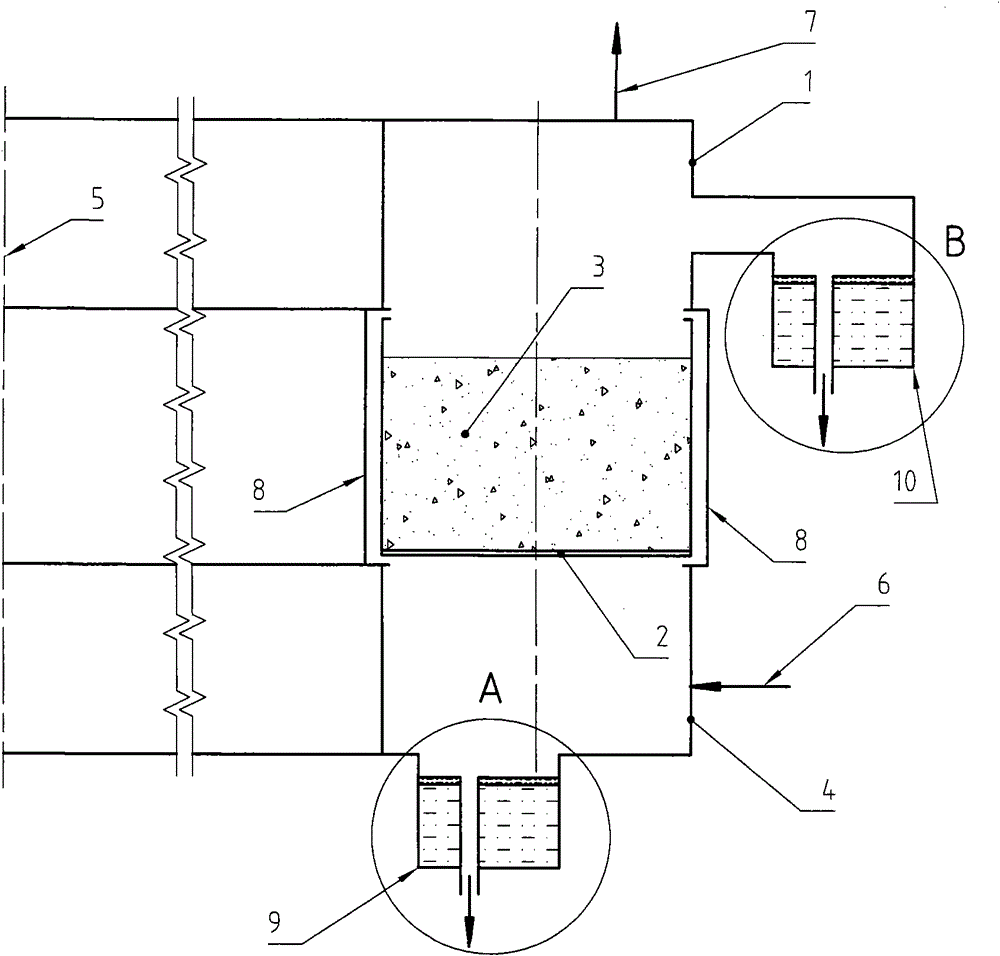
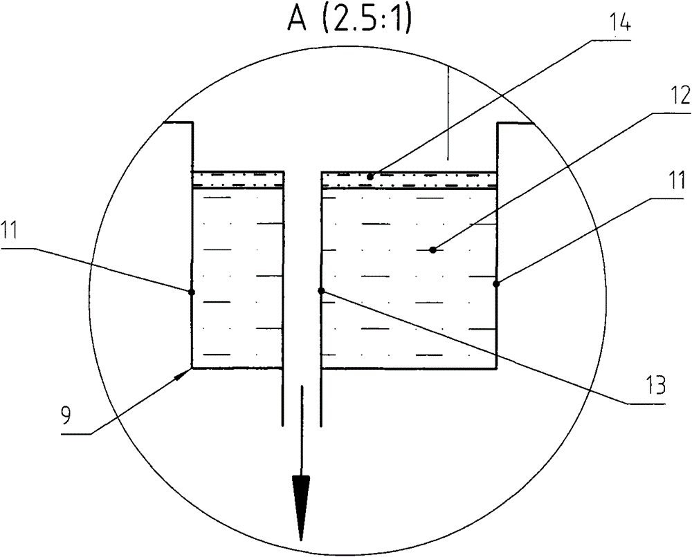
[0046] Figure 5 What is shown is also a schematic layout diagram of the general structure of an annular movable grate retort furnace for extracting shale oil and gas from oil shale, except that its sealing device adopts a liquid sealing device, and the rest are the same as figure 1 situation is roughly the same. Wherein, 1 is the upper cover of this dry distillation furnace. 2 is the moving grate of this carbonization furnace, and this moving grate rotates around center line 5. 3 is the oil shale laid on the movable grate 2. 4 is the lower cover of this dry distillation furnace. The heat-carrying gas or furnace gas enters through the intake pipe 6, passes through the shale oil layer and is discharged through the exhaust pipe 7, and its sealing task is completed by the liquid sealing device. In this annular moving grate type carbonization furnace, a total of 4 groups of liquid seal devices are used. Shown in Part...

Embodiment 3

[0050] Example 3, such as Figure 7 , Figure 8 shown.

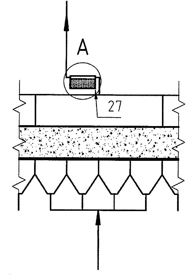
[0051] Figure 7 Shown is a part of the process layout of a dynamic grate retort for extracting shale oil and gas from oil shale; Figure 8 yes Figure 7 Enlarged view of middle A. Figure 7 , Figure 8 Commonly used in this embodiment.

[0052] The purpose of listing this embodiment is to demonstrate the situation that the oil vapor absorbing tank 27 is arranged as close as possible to the furnace gas outlet of the retort furnace. from Figure 7 , Figure 8 It can also be seen from the figure that there is a process of passing the surface of the absorbing liquid during the output of the furnace gas. At this time, part of the oil vapor in the furnace gas can be captured, thereby reducing the concentration of oil vapor in the furnace gas to reduce Or avoid the problem of oil hanging in the furnace gas during the transportation process. As for other details of the oil vapor absorption tank 27, please refer to the...


PUM


Abstract

The invention relates to a method for extracting oil vapor from gases of a dry distillation furnace and belongs to the technical field of extracting shale oil gas from oil shale. The method is characterized in that: an oil gas absorption groove is arranged on a part directly communicated with the dry distillation furnace; absorption liquid is accommodated in the absorption groove; the temperature of the absorption liquid is lower than that of the furnace gases; and the temperature difference is more than or equal to 20 DEG C. By the method, the oil gas component can be absorbed from the furnace gases in the dry distillation furnace; output quantity and treatment quantity of the furnace gases can be reduced; energy is saved; investment for the first time can be reduced; partial pressure of dry gases, mainly comprising methane, in the furnace gases can be increased; high dryness of the furnace gases can be maintained; and under the same condition, yield of the dry distillation furnace, particularly the yield of the oil gas contained in the oil shale, is increased; operation cost is reduced; and resources are saved. Therefore, the method is particularly applicable to the dry distillation furnace of the oil shale.

Description

Technical field [0001] The present invention involves a method of extracting oil from the furnace gas from the dry distillation furnace, which belongs to the technology field of extracting shale oil and gas from oil shale. Background technique [0002] The development and utilization of oil shale is an important topic at present.In order to extract shale oil and combustible gas from the oil shale, the current method is usually used: first obtaining the furnace gas containing shale oil vapor and combustible gas, and then sent the furnace gas into a special separation device., Separate shale oil and combustible gas from the furnace gas, and then use them separately. [0003] The shortcomings of the existing technology are: [0004] 1. In the furnace gas before entering the separation device, the concentration of shale oil vapor is high, and it is easy to produce the condensation wall of shale oil vapor. [0005] 2. In the process of separating shale oil, the furnace gas should be c...

Claims


Application Information

Patent Timeline
Patent Type & Authority Patents(China)
IPC IPC(8): C10B53/06
Inventor 姚朝胜魏新民衣忠德黄东生钱纲
Owner SHANDONG PROVINCE METALLURGICAL ENG CO LTD
Why Eureka
Try Eureka