Supercharge Your Innovation With Domain-Expert AI Agents!

Dust removal washing and purification device for industrial waste gas

A purification device and industrial waste gas technology, which is applied in the direction of combined devices, chemical instruments and methods, and dispersed particle filtration, etc. It can solve the problems of unsmooth airflow, difficult processing and manufacturing, and failure to meet dust removal standards in the dust removal system, achieving maintenance-free Effects that clean up, save manufacturing costs, and are less difficult to manufacture

Inactive Publication Date: 2013-12-25
习亚丰
View PDF5 Cites 0 Cited by
  • Summary
  • Abstract
  • Description
  • Claims
  • Application Information

AI Technical Summary

Problems solved by technology

The disadvantages of this structure are 1. The impurities in the circulating water will block the nozzle, and it is often necessary to maintain and replace or must use purified or tap water to operate.
2. The pressure of the water flow is high, and a sufficiently large power system must be used. 3. The water pressure formed by the spray is too high, which will cause the air flow in the entire dust removal system to be blocked, and the flue gas will overflow from other outlets without passing through the dust removal system. Poor dust removal effect
[0004] A small number of other dust collectors that do not use a spray structure or complex structures are very difficult to process and manufacture. If the processing process is not strictly controlled, the entire dust collector will be scrapped; or it cannot meet the dust removal standards stipulated by the state at all; Large, inconvenient installation, maintenance, and replacement will also bring great safety hazards

Method used


Image

  • Dust removal washing and purification device for industrial waste gas
  • Dust removal washing and purification device for industrial waste gas
  • Dust removal washing and purification device for industrial waste gas

Examples


Embodiment Construction

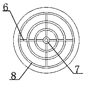
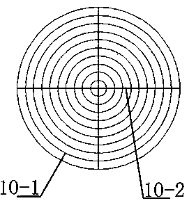
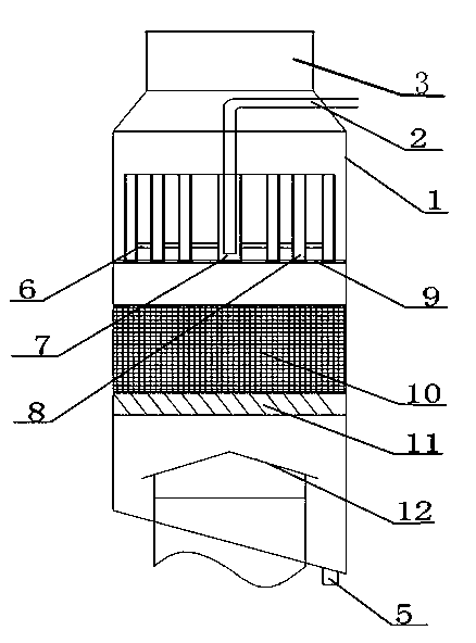
[0024] as attached figure 1 , 2 , 3, an embodiment of the present invention is an industrial waste gas dedusting, washing and purifying device, which includes a housing 1, and a water inlet pipe 2 and a sewage discharge pipe 5 provided as a set, the upper end of the housing 1 is a flue gas outlet 3, and the lower part of the housing 1 exhausts smoke A water blocking cap 12 is provided on the exhaust gas outlet of the equipment. The upper part of the shell 1 is provided with a water flow buffer and equal distribution structure, which includes a bracket 9 fixed on the shell 1, and a two-way water flow equalizer 8 and a water-bearing overflow bucket 7 arranged on the bracket 9; The two-way water flow equalizer 8 is composed of 10-20 concentric ring-shaped barrels connected to each other, and the water-bearing equal-split overflow barrel 7 is arranged in the center of the support 9, that is, the ring-shaped barrels of the two-way water flow equalizer 8 The central part of the wa...


PUM


Abstract

The invention relates to a dust removal washing and purification device for industrial waste gas, which comprises a shell, a water inlet pipe and a discharge pipe, wherein a water flow buffering and splitting structure is arranged on the upper part in the shell and comprises a support, a two-way water flow splitter and a water bearing splitting overflow barrel; the two-way water flow splitter consists of 10 to 20 concentric annular barrels which are communicated mutually; the water bearing splitting overflow barrel is arranged in the center of the support and is communicated with the two-way water flow splitter; the water inlet pipe extends into the lower middle part of the water bearing splitting overflow barrel; a filter screen array which is arranged vertically and uniformly, consists of filter screens and has a concentric cylindrical shape is arranged below the water flow buffering and splitting structure; and a gas water diversion plate array which consists of obliquely arranged gas water diversion plates is arranged at the lower end of the filter screen array. The dust removal washing and purification device has a more scientific and reasonable structure, and has the advantages of good effect of removing micro granules, high efficiency of desulfuration and dust removal, small investment, low running cost and the like.

Description

technical field [0001] The invention relates to an industrial waste gas dust removal washing purification system. technical background [0002] During the 12th Five-Year Plan period, the country vigorously advocated energy conservation and emission reduction. This is an urgent task to implement the scientific development concept and transform the mode of economic development. It is a practical action for our country to deal with global climate change. Therefore, we must adhere to environmental protection, carry out in-depth emission reduction and national action, and advocate green consumption. At present, in industrial production, there are many kinds of dedusting and desulfurization devices used to treat process exhaust emissions. The most commonly used ones are mostly wet dedusting devices. Some wet dedusting devices have poor dedusting effect and low desulfurization efficiency, especially the ability to remove micro particles is poor. [0003] At present, most of the we...

Claims


Application Information

Patent Timeline
Patent Type & Authority Patents(China)
IPC IPC(8): B01D50/00B01D47/00B01D46/10
Inventor 习亚丰
Owner 习亚丰
Features
  • R&D
  • Intellectual Property
  • Life Sciences
  • Materials
  • Tech Scout
  • Unparalleled Data Quality
  • Higher Quality Content
  • 60% Fewer Hallucinations
Learn More