
Numerical control universal worm grinder

A worm grinding machine, a universal technology, applied in the direction of grinding machines, grinding/polishing equipment, metal processing equipment, etc., can solve the problem of not being able to grind cone enveloping toroidal worms, ordinary cylindrical worms, or toruses. Worm and other problems, to achieve the effect of ingenious design, good rigidity, and reasonable workpiece clamping

Inactive Publication Date: 2011-09-28
宝鸡市广环机床有限责任公司
View PDF10 Cites 14 Cited by
  • Summary
  • Abstract
  • Description
  • Claims
  • Application Information

AI Technical Summary

Problems solved by technology

[0004] Existing ordinary worm grinding machines can only grind ordinary cylindrical worms, but cannot grind toroidal worms
Ordinary toroidal worm grinding machines can only grind plane secondary enveloping toroidal worms (TOP type), and cannot grind ordinary cylindrical worms, nor can they grind cone-enveloping toroidal worms
There is no universal worm grinder for grinding various worms so far

Method used


Image

  • Numerical control universal worm grinder
  • Numerical control universal worm grinder
  • Numerical control universal worm grinder

Examples


Embodiment Construction

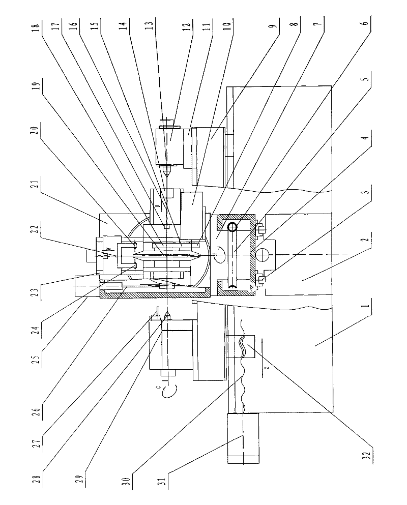
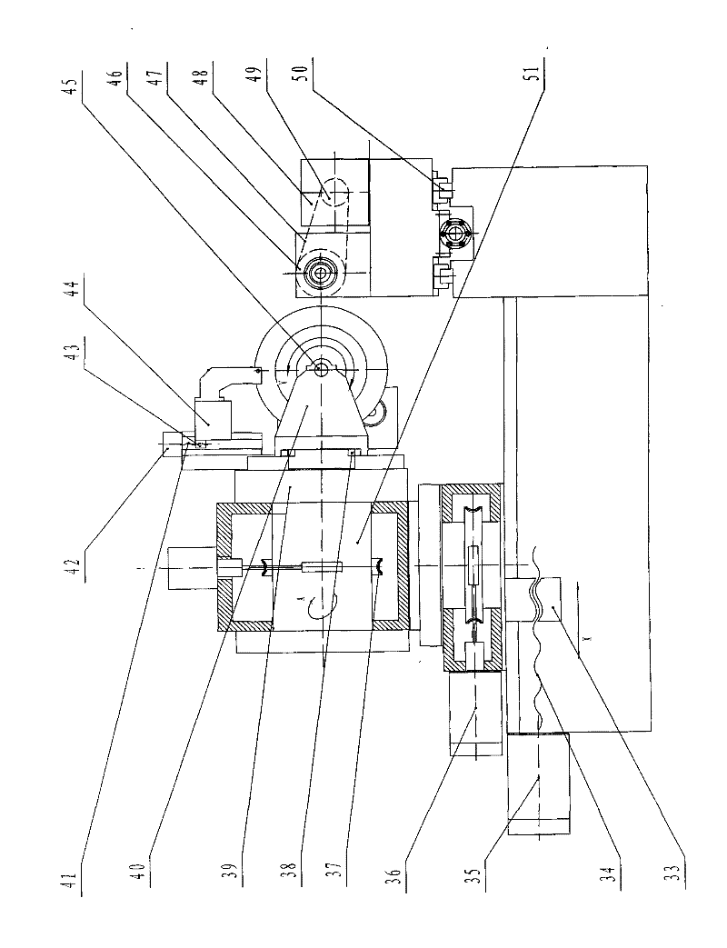
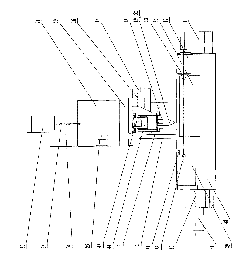
[0025] Attached below figure 1 , 2 , 3 describe an embodiment of the present invention.

[0026] A numerically controlled universal worm grinding machine, comprising a front bed 1, a rear bed 2, a slide table 9, a headstock 29, a tailstock 12, a knife table 4 and a grinding head 52.

[0027] The front end of the rear bed 2 is fixedly connected to the inside of the middle of the front bed 1 to form a "T" shape layout; the upper end of the front bed 1 is equipped with a Z-axis guide rail 50, and the slide table 9 is located on the Z-axis guide rail 50 , and the nut I32 installed on the lower end surface of the sliding table 9 is connected with the Z-axis ball screw 30, and the Z-axis servo motor 31 connected with the Z-axis ball screw 30 drives the sliding table 9 to move linearly along the Z-axis guide rail 50; The left end of slide table 9 is equipped with headstock 29, and headstock top 28 is equipped with on the right end of headstock 29, and the synchronous toothed pulley...


PUM


Abstract

The invention relates to a numerical control universal worm grinder. The numerical control universal worm grinder is characterized in that a rear grinder body and a front grinder body are fixedly connected into a T-shaped layout; the front grinder body is provided with a Z-axis guide rail, and a sliding platform is positioned on the Z-axis guide rail and is driven to move by virtue of a Z-axis servo motor and a lead screw; and a head frame and a tail frame are arranged on the sliding platform, a workpiece is supported between the head frame and the tail frame, and a C-axis servo motor drives the workpiece to rotate by virtue of a synchronous tooth-shaped belt, a shifting fork and a chuck on the workpiece. The rear grinder body is provided with an X-axis guide rail, a cutter platform is positioned on the X-axis guide rail and is driven to move by virtue of an X-axis servo motor and a lead screw; a rotary platform surface is arranged on the cutter platform and is driven to rotate by a B-axis servo motor; the rotary platform surface is fixedly provided with a grinding head vertical column which is provided with a rotary sleeve, and the front end of the rotary sleeve is provided with a front flange which is provided with a grinding head; and the rotary sleeve and the front flange are driven to rotate by virtue of an A-axis motor, and a grinding wheel on the grinding head is drivenby a grinding wheel motor. In the numerical control universal worm grinder, the axial parallel motion or curvilinear motion of the grinding wheel relative to the workpiece and rotary motion of the workpiece and the grinding wheel can be realized, and the grinding of the common cylindrical worm and a ring-surface worm is realized.

Description

technical field [0001] The invention belongs to the technical field of transmission worm processing equipment manufacturing, and in particular relates to a numerically controlled universal worm grinding machine. Background technique [0002] Worm drive has the characteristics of compact structure, large transmission ratio, large transmission power range, stable operation, self-locking, etc., and is widely used in the field of mechanical transmission. According to the structural characteristics and processing principle, the worm drive can be divided into two categories: ordinary cylindrical worm drive and toroidal worm drive. [0003] Ordinary cylindrical worm drives include Archimedes cylindrical worm (ZA type), involute cylindrical worm (ZI type), normal straight profile worm (ZN) type, cone enveloping cylindrical worm (ZK type) and arc cylindrical Worm (ZC type) five subcategories. Toroidal worm drives include straight profile toroidal worm (TSL type), planar double enve...

Claims


Application Information

Patent Timeline
IPC IPC(8): B24B25/00
Inventor 胡万良宋广维郭喜鹊杨军
Owner 宝鸡市广环机床有限责任公司
Learn More