
Thickness and convexity detection device for plates and strips

A detection device, plate and strip technology, applied in the nuclear technology application field, can solve the problems of instrument dynamic performance decline, swing frequency not too fast, complex mechanical structure, etc., to improve dynamic measurement accuracy, improve dynamic detection performance, and simplify machinery structure effect

Active Publication Date: 2011-09-28
TSINGHUA UNIV
View PDF3 Cites 15 Cited by
  • Summary
  • Abstract
  • Description
  • Claims
  • Application Information

AI Technical Summary

Problems solved by technology

[0004] First, the afterglow is long, the photodiode is not resistant to radiation, and its life is short. It has high requirements on the temperature of the working environment, and the working environment needs constant temperature control.
[0005] Second, since different ray sources share a row of detectors, a rotating shutter is required to allow the two X-ray sources to emit X-rays alternately, the mechanical structure is complex, and there is vibration interference
[0006] Third, since the rays of the two X-ray sources are measured successively by the same row of detectors, the distance between the detection positions of the two X-ray sources on the steel plate is related to the running speed of the steel plate, and the thickness reconstruction of the steel plate is based on two rays The measurement data of the source is obtained, so the measurement accuracy decreases when the steel plate runs at a high speed
[0007] In addition, there are also gas ionization chamber detectors (as described in the product information of German IMS company), but the volume of the ionization chamber used is large, so the resolution cannot meet the requirements of the steel mill, and the C-shaped frame needs to go back and forth along the width of the steel plate. swing to increase resolution
On the one hand, it makes its machinery and control system complicated; at the same time, due to the heavy weight of the C-shaped frame, the swing frequency cannot be too fast, generally 1.5Hz to 2Hz, which makes it difficult to calculate the thickness data on the same cross-section when the steel plate is moving. From two different sections (several meters to tens of meters apart), the dynamic performance of the instrument is reduced
And in terms of the ray source, because the X-ray source used by it has a small opening angle, it cannot cover the width of the steel plate. One projection in the width direction of the steel plate requires two ray sources. If the ray source used to obtain another projection is added, A total of 4 ray sources are required, and the structure is complex

Method used


Image

  • Thickness and convexity detection device for plates and strips
  • Thickness and convexity detection device for plates and strips
  • Thickness and convexity detection device for plates and strips

Examples


Embodiment Construction

[0017] The specific content of the present invention is described in detail below in conjunction with accompanying drawing:

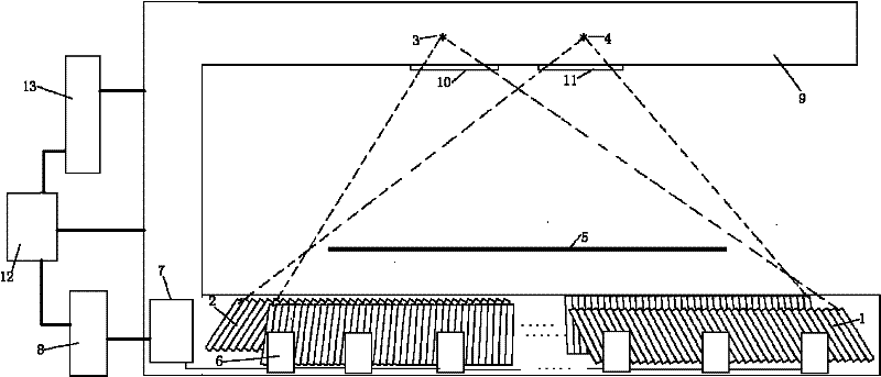
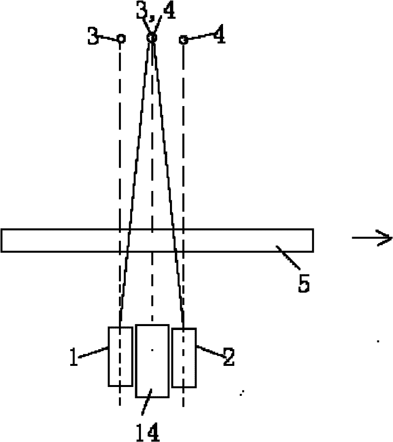
[0018] The present invention proposes a thickness convexity detection device for strips, as in figure 1 As shown, it includes a C-frame 9, two ray sources 3 and 4 installed in the upper arm of the C-frame at intervals along the width direction of the steel plate, installed in the lower arm of the C-frame of the protruding meter and spaced apart along the moving direction of the plate and strip Arranged two rows of high-voltage gas-filled ionization chamber detector arrays 1, 2, and collimators 10, 11 installed under the two radiation sources, the collimator makes the radiation of each radiation source only irradiate the corresponding row of detectors Array, the preamplifier module 6 that links to each other with described detector array, the data acquisition machine 7 that links to each other with above-mentioned preamplifier module, the data processing...


PUM


Abstract

The invention relates to a thickness and convexity detection device for plates and strips and belongs to the field of nuclear technology application. The device comprises a C-shaped frame, two ray sources which are arranged in an upper arm of the C-shaped frame along a width direction of a steel plate to be detected at an interval, two rows of high-pressure aeration ionization chamber detector arrays which are arranged in a lower arm of the C-shaped frame along a motion direction of a plate or a strip at intervals, a collimator which is arranged below the two ray sources and used for making each ray source emit a ray to the corresponding one row of detector array, a preamplifier connected with the detector arrays, a data acquirer connected with the preamplifier, a data processing and display computer connected with the data acquirer, a steam service system for guaranteeing running of a system and monitoring, and a control system. The thickness and convexity detection device is simple in mechanical structure and high in dynamic measurement precision; furthermore, the detector has the advantages of low temperature drift, high radiation resistance, high space resolution, high cost performance and the like.

Description

technical field [0001] The invention belongs to the application field of nuclear technology, in particular to a detection device for the thickness, convexity and shape of plates and strips on industrial hot rolling or cold rolling production lines. Background technique [0002] The crown meter is the key equipment for the production and control of strips, and plays an important role in improving the output and quality of strips. Due to the high rolling temperature of hot-rolled steel plates (above 800°C) and the presence of dust and water vapor in the environment, the non-contact ray measurement method has great advantages. The detector performance of the ray method convexity meter is one of the key factors to determine the measurement accuracy and detection speed of the convexity meter. [0003] Existing convexity meters use a single row of solid detectors (as described in the product information of Thermo Electric Corporation of the United States). Although they have the ...

Claims


Application Information

Patent Timeline
Patent Type & Authority Applications(China)
IPC IPC(8): G01B15/02G01B15/08G01B15/04
CPCG01B15/02G01B15/04G01B15/025G01N23/02G01N2223/633
Inventor 吴志芳安继刚张玉爱苗积臣李立涛邢桂来王立强王振涛刘锡明郑健黄毅斌郭肖静谈春明
Owner TSINGHUA UNIV
Learn More