Spiral waveform cutting metal wire as well as manufacturing method and equipment thereof

A production method and metal wire technology are applied to stone processing equipment, manufacturing tools, and other household appliances, etc., which can solve problems such as metal monofilament breakage, gemstone line mark defects, affecting cutting speed and slicing quality, and reduce wear and tear. The effect of improving surface quality

Active Publication Date: 2011-10-05
ZHENJIANG NAISI ADVANCE MATERIALS
View PDF7 Cites 48 Cited by
  • Summary
  • Abstract
  • Description
  • Claims
  • Application Information

AI Technical Summary

Problems solved by technology

[0003] The linear metal monofilament can only be mechanically brought into the mortar through the smooth surface at high speed, and during the cutting process, the abrasive in the mortar is easy to peel off from the cutting wire, which affects the cutting speed and slice quali

Method used


Image

  • Spiral waveform cutting metal wire as well as manufacturing method and equipment thereof
  • Spiral waveform cutting metal wire as well as manufacturing method and equipment thereof
  • Spiral waveform cutting metal wire as well as manufacturing method and equipment thereof

Examples


Embodiment 1

[0026] Such as Figure 6 As shown, the metal wire production equipment of this embodiment includes a pay-off reel 1, a deformation gear 2, a first twist limiting wheel 3, a second twist limiting wheel 4, a flywheel ring 5, a shaft head 6, a bracket 7, a motor 8, a Wire reel 9, traction power part; Wherein: shaft head 6 is fixed on the two ends of flywheel ring 5, and shaft head 6 is fixed on the support 7, and shaft head 6 is driven by motor 8, and take-up reel 9 and pay-off reel 1 are arranged on On the bracket 7, the two ends of the flywheel ring 5 are respectively provided with a first torsion limiting wheel 3 and a second torsion limiting wheel 4, the deformation gear 2 is located between the pay-off reel 1 and the first torsion limiting wheel 3, and the take-up reel 9 is located at After the second torsion limiting wheel 4, a traction power member is provided on the take-up reel 9, and a wire passing wheel 10 is provided between the take-up reel 9 and the second torsion l...

Embodiment 2

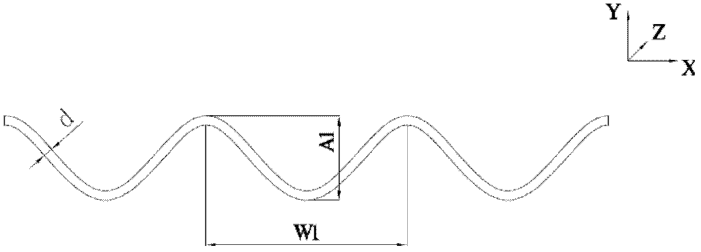
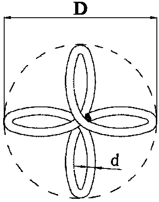
[0034] In this embodiment, the diameter of the metal wire is d=0.05mm, and the periodic waveform formed is wavelength W1=15mm, wave height A1=0.4mm=helix diameter D.

[0035] Such as image 3 Shown is a schematic representation of the y-z plane for two wavelength periods, with a rotation of 90 degrees in each half wavelength period. The produced metal wire is a periodic corrugated metal wire that rotates along the axial center line into a helical shape, and the crests and troughs of the metal wire are distributed symmetrically along the axial center line.

[0036] The angle of wire rotation is determined by how much twist is added to the unit length. The traction speed of the traction power part on the take-up reel 9 is 60m / min in this implementation, and the rotation speed of the flywheel ring 5 is 2000 revolutions / min. 0.033 twists were added to the length of wire to obtain a wire pitch of 30 mm.

[0037] Other implementation conditions are identical with embodiment 1.

Embodiment 3

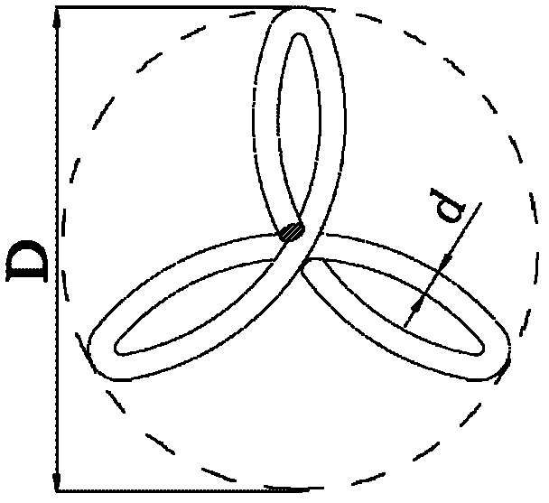
[0039] In this embodiment, the diameter of the metal wire is d=0.5mm, and the periodic waveform formed is wavelength W1=20mm, wave height A1=0.315mm=helix diameter D.

[0040] Such as Figure 4 Shown is a schematic representation of the y-z plane for three wavelength periods, with a rotation of 60 degrees in each half wavelength period. The produced metal wire is a periodic corrugated metal wire that rotates along the axial center line into a helical shape, and the crests and troughs of the metal wire are distributed symmetrically along the axial center line.

[0041] The angle of wire rotation is determined by how much twist is added on the unit length. The traction speed of the traction power part on the take-up reel 9 in this implementation is 60m / min, and the rotation speed of the flywheel ring 5 is 1000 revolutions / min. Adding 0.017 twists to the length of the wire yields a wire pitch of 60 mm.

[0042] Other implementation conditions are identical with embodiment 1.


PUM

PropertyMeasurementUnit
Diameteraaaaaaaaaa
Wavelengthaaaaaaaaaa

Abstract

The invention discloses a spiral waveform cutting metal wire as well as a manufacturing method and equipment thereof. The metal wire is a spiral waveform metal wire formed by rotating a periodic waveform metal wire along an axial center line, a wave crest and a wave trough of the metal wire are distributed along the axial center line, and a spiral diameter of the metal wire is equal to a wave height. The spiral waveform cutting metal wire disclosed by the invention can provide better mortar abrasive carrying capability in the process of cutting a rigid material through a stereostructure of the spiral waveform cutting metal wire, and the abrasive is not easily stripped from a cutting wire, therefore, the production speed and efficiency of technical processing of cutting and slicing silicon materials, precious stones and the like are greatly improved, and the surface quality of the sliced materials can be also improved.

Description

technical field [0001] The invention relates to a cutting wire, a manufacturing method and equipment, in particular to a spiral wave cutting wire and a manufacturing method and equipment. Background technique [0002] In the division and slicing process of hard materials such as monocrystalline silicon, polycrystalline silicon, and gemstones in the field of electronics and solar energy, the most used method is to use linear metal monofilaments to move in one direction or reciprocating under a certain tension. way to split slices. When the metal monofilament is moving, through the mortar transportation and injection system, before the metal monofilament contacts with the silicon rod and other objects to be cut, the mortar containing extremely hard abrasive particles is sprayed on the metal monofilament, and the metal monofilament is brought into the cutting process. Through the continuous grinding process of extremely high hardness abrasive particles and silicon rods, gemsto...

Claims


Application Information

Patent Timeline
IPC IPC(8): B28D5/04B21F3/00B21F45/00
Inventor 闵学刚
Owner ZHENJIANG NAISI ADVANCE MATERIALS
Why Eureka
Try Eureka