LED fluorescent lamp

A technology of LED fluorescent lamps and blue light chips, applied in the field of LED fluorescent tubes, can solve problems such as heat can not be exported in time, voltage is difficult to light up, circuit board deformation, etc., to avoid LED brightness attenuation, improve brightness and color rendering, and avoid contact Effect of Face Gap

Inactive Publication Date: 2011-10-05
昆山冠辉精密电子有限公司
View PDF0 Cites 1 Cited by
  • Summary
  • Abstract
  • Description
  • Claims
  • Application Information

AI Technical Summary

Problems solved by technology

Traditional fluorescent lamps have the following defects: A. The fluorescent tube contains heavy metals such as mercury. The heavy metals released after bursting will cause environmental pollution and harm to the human body, which does not meet the current environmental protection requirements; B. The light is not stable enough. It will flicker according to the working frequency of the power grid, which is harmful to human eyes; C. It is difficult to light up when the voltage is low when it is started by a large current; The converter structure has low power and high power consumption, resulting in waste of energy
However, the existing LED fluorescent tubes have the following defects: A. Generally, 3528 series white LEDs are used. Due to the limitation of brackets and chips, the luminous flux generally cannot exceed 10LM, and the color rendering cannot reach more than 90 between 70-80; B. The circuit board with LED soldered is separated from the shell, and the heat is transmitted to the shell by the circuit board and air, which seriously hinders the conduction of heat and shortens the life of the LED. Between the board and the case, apply thermal paste or add a heat-conducting silicone pad to quickly conduct heat to the case. This assembly has the following disadvantages: First, if the thermal paste is applied unevenly during the assembly process, the silicone heat-conducting pad is uneven or The deformation of the circuit board will cause the heat to not be exported in time and affect the service life of the fluorescent tube. Second, due to the different thermal conductivity of each object and when the two objects are in contact, there will be a gap between the contact surfaces, which affects the heat. Fast conduction; C. The assembly process is more complicated, cumbersome and inefficient

Method used


Image

  • LED fluorescent lamp
  • LED fluorescent lamp
  • LED fluorescent lamp

Examples


Embodiment

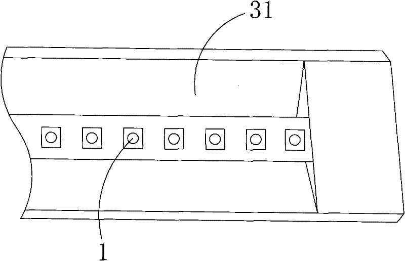
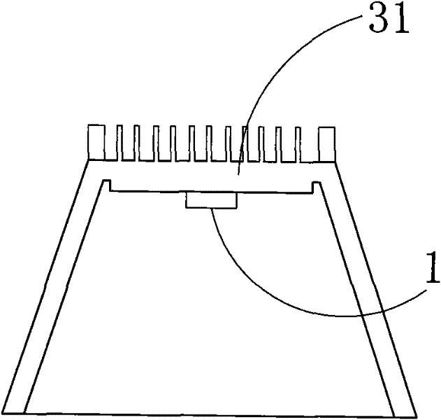
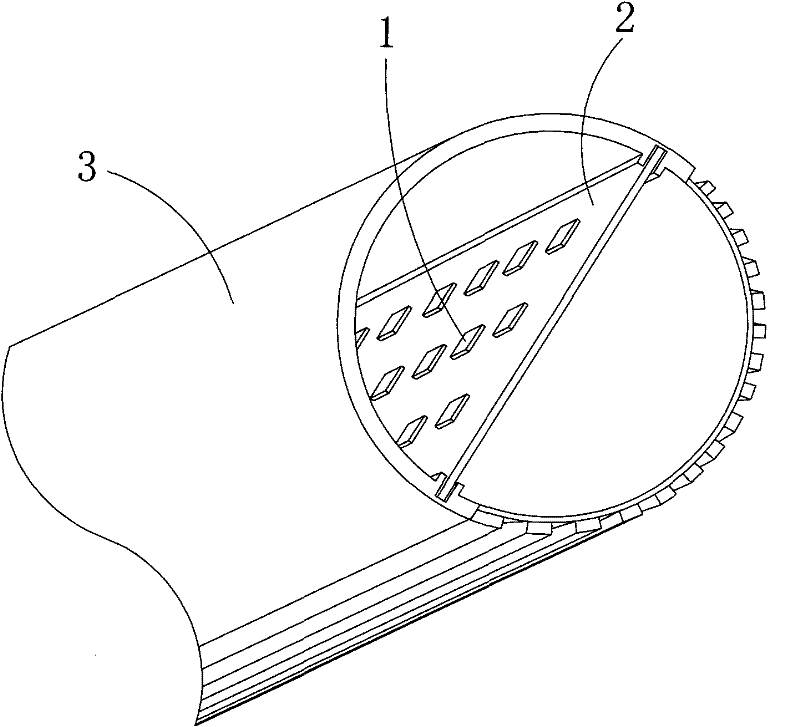
[0015] Embodiment: an LED fluorescent tube, comprising a casing, several LEDs 1 and a circuit board for electrically connecting the LEDs, the casing is composed of a heat dissipation installation base 31 and a light transmission cover, and the circuit board is integrally formed on the heat dissipation The installation base, the LED1 is soldered to the heat dissipation installation base and electrically connected to the circuit board, and the heat dissipation installation base is buckled with the light transmission cover. That is, the heat dissipation installation base 31 of the housing of the LED fluorescent tube in this embodiment is an integrated heat dissipation installation base integrating heat dissipation and circuit boards, which can improve heat dissipation efficiency, allow the heat generated by the LED to be quickly conducted, and reduce light emission. The attenuation and aging of the chip due to excessive temperature. In this way, it can be avoided that the traditi...


PUM


Abstract

The invention discloses a light-emitting diode (LED) fluorescent lamp, which comprises a shell, a plurality of LEDs and a circuit board which is electrically connected with the LEDs, wherein the circuit board is formed on the shell integrally; and the LEDs are welded on the shell and are electrically connected with the circuit board. The shell of the LED fluorescent lamp is an integrated shell which integrates heat dissipation and the circuit board, and can improve the radiating efficiency, so that heat generated by the LEDs can be conducted out quickly to reduce the attenuation aging of a luminous chip due to overhigh temperature; and the shell integrates the heat dissipation and the circuit board, so the assembly process can be simplified substantially, namely the LEDs are needed to be welded on the integrated shell only without coating heat conducting glue, adding heat conducting silica gel mats, assembling the circuit board like the conventional LED fluorescent lamp. Each LED monomer on the LED fluorescent lamp has a polycrystal-parallel encapsulation structure, so the luminance and color-rendering properties of the white LEDs can be improved effectively.

Description

technical field [0001] The invention relates to a fluorescent lamp tube, in particular to an LED fluorescent lamp tube. Background technique [0002] The traditional fluorescent lamp emits ultraviolet light through the conduction of the gas (argon and mercury vapor) between the filaments, so that the phosphor powder coated on the inner wall of the lamp tube emits soft visible light. Traditional fluorescent lamps have the following defects: A. The fluorescent tube contains heavy metals such as mercury. The heavy metals released after bursting will cause environmental pollution and harm to the human body, which does not meet the current environmental protection requirements; B. The light is not stable enough. It will flicker according to the working frequency of the power grid, which is harmful to human eyes; C. It is difficult to light up when the voltage is low when it is started by a large current; The inverter structure has low power and high power consumption, resulting ...

Claims


Application Information

Patent Timeline
Patent Type & Authority Applications(China)
IPC IPC(8): F21S2/00F21V15/02F21V19/00F21V23/00F21V17/00F21Y101/02F21K9/20F21Y115/10
Inventor 周金成
Owner 昆山冠辉精密电子有限公司
Why Eureka
Try Eureka