Heat radiation type flexible circuit board

A flexible circuit board, heat dissipation technology, used in printed circuit parts, metal pattern materials, electrical connection printed components, etc. The effect of improving performance, prolonging service life and meeting heat dissipation requirements

Active Publication Date: 2011-10-05
博罗县精汇电子科技有限公司
View PDF4 Cites 18 Cited by
  • Summary
  • Abstract
  • Description
  • Claims
  • Application Information

AI Technical Summary

Problems solved by technology

[0003] The present invention provides a new structure design of flexible circuit board, which changes the existing single-sided board into double-sided board, and uses plated through holes (PTH) to connect, and then uses high thermal conductivity adhesive to connect the bottom layer and the metal base together to solve the problem. Technical problems that cannot meet the requirements of heat resistance and high thermal conductivity in the prior art

Method used


Image

  • Heat radiation type flexible circuit board
  • Heat radiation type flexible circuit board
  • Heat radiation type flexible circuit board

Examples


Embodiment 1

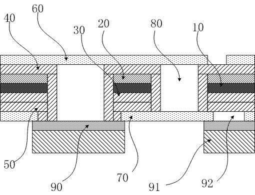
[0009] Embodiment 1: by figure 1 It can be seen from the figure that this heat-dissipating flexible circuit board includes a base layer film 10, the two sides of the base layer film 10 respectively cover the top layer conductive layer 20 and the bottom layer conductive layer 30, and the top layer conductive layer 20 and the bottom layer conductive layer 30 are respectively connected to the ground wires of their respective layers, A top metal layer 40 is plated on the top conductive layer 20, a bottom metal layer 50 is plated on the bottom conductive layer 30, a top cover film 60 is laid on the top metal layer 40, and the bottom conductive layer 30 and then lay the bottom cover film 70, the circuit board also includes a plated through hole 80, the plated through hole 80 is connected to the ground wire of the top conductive layer 20 and the ground wire of the bottom conductive layer 30; this circuit board also includes a high thermal conductivity The adhesive layer 90 and the me...

Embodiment 2

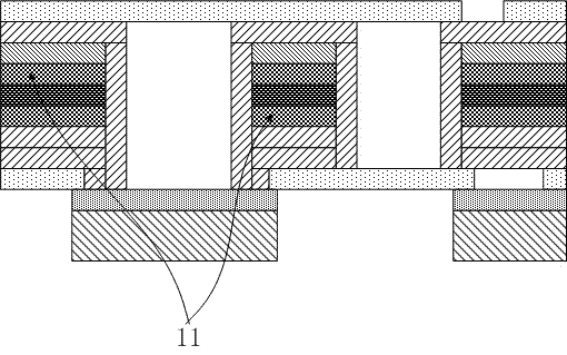
[0013] Embodiment 2: by figure 2 It can be seen from the figure that the two sides of the base layer film 10 are bonded to the top conductive layer 20 and the bottom conductive layer 30 respectively by the adhesive 11, and the adhesive 11 is an acrylic adhesive or a modified epoxy adhesive. The base film 10, the top conductive layer 20, the bottom conductive layer 30 and the adhesive 11 connect the top conductive layer together through the plated through hole 80, and the top metal layer 40 and the bottom metal layer 50 are used as the electroplating layer when the plated through hole is used, and other The structure and principle are the same as those in Embodiment 1, and will not be repeated here.

[0014] This design provides a brand-new structural solution to solve the above problems: change the existing single-sided panel into a double-sided panel, and lay a whole board of copper foil, aluminum foil, silver foil or grid copper foil, aluminum foil, silver foil on the botto...


PUM


Abstract

A heat radiation type flexible circuit board comprises: a basement membrane (10), a top conductive layer (20), a bottom conductive layer (30), a top electroplating metal layer (40), a bottom electroplating metal layer (50), a top cover membrane (60), and a bottom cover membrane (70). The circuit board also comprises: a PTH (80) which is connected with ground wires of the top conductive layer (20)and the bottom conductive layer (30); a high heat-conducting glue layer (90) and a metal substrate (91), wherein the metal substrate (91) is covered on the bottom cover membrane (70) through the high heat-conducting glue layer (90) and the metal substrate (91) is connected with the bottom electroplating metal layer (50) through a bottom pad (92) so that a heat radiation effect can be achieved. The above structure is adopted in the invention so that heat resistance and heat-conducting property of the circuit board with the novel structure can be greatly raised. Therefore, heat radiation requirements of a large power LED circuit board can be completely satisfied so that service life of products can be prolonged.

Description

technical field [0001] The invention relates to basic circuit components, in particular to the structural design of a circuit flexible circuit board with excellent heat dissipation. Background technique [0002] At present, the application of high-power LED (light-emitting diode) is becoming more and more popular. There are more and more applications of high-power light-emitting diodes in automobile lights. In the past, the aluminum substrate of the rigid circuit board was very good in heat dissipation, but due to assembly The consistency and reliability of the circuit board are relatively poor, and the assembly space needs to be relatively large, so the use of flexible circuit boards to replace the original aluminum-based rigid circuit boards has become a new direction for the development of the electronics and electrical component industries and the circuit board industry. At present, LED lamps generally adopt the structure of a single-sided flexible circuit board with pre...

Claims


Application Information

Patent Timeline
Patent Type & Authority Applications(China)
IPC IPC(8): H05K1/02H05K1/09H05K1/11
Inventor 叶夕枫
Owner 博罗县精汇电子科技有限公司
Why Eureka
Try Eureka