Device for preparing nano fiber twisted structure

A stranded wire and fiber technology, which is applied in the field of devices using centrifugal electrospinning technology to prepare nanofiber stranded wire structures, can solve the problem of insufficient order of overlapping fiber bundles, poor controllability of the number of stranded wire structure nanofibers, and spinning voltage High-level problems, to achieve the effect of good structure and shape of stranded wires, high degree of splicing sequence, and accurate and controllable number

Inactive Publication Date: 2013-01-02
QINGDAO UNIV
View PDF5 Cites 2 Cited by
  • Summary
  • Abstract
  • Description
  • Claims
  • Application Information

AI Technical Summary

Problems solved by technology

[0003] At present, there are not many reports in the literature on the preparation of nanofiber strand structures by electrospinning technology. The existing reports are mainly through the improvement of the collection method to obtain the helically wound strand structure of multiple fibers. For example, Paul D.Dalton et al. (Polymer46 (2005) 611-614) obtained the stranded wire structure of nanofibers by using a double-ring collection-rotation method; Lu-Qi Liu et al. The stranded wire structure of nanofibers has been obtained by the method; in addition, the stranded wires can also be prepared by alternating electric field (Appl. However, these methods generally have outstanding shortcomings such as high spinning voltage, insufficient order of the overlapping fiber bundles before the formation of the strand structure, and poor controllability of the number of strand structure nanofibers.

Method used


Image

  • Device for preparing nano fiber twisted structure
  • Device for preparing nano fiber twisted structure
  • Device for preparing nano fiber twisted structure

Examples


Embodiment 1

[0014] Example 1: Preparation of orderly lapped fibers.

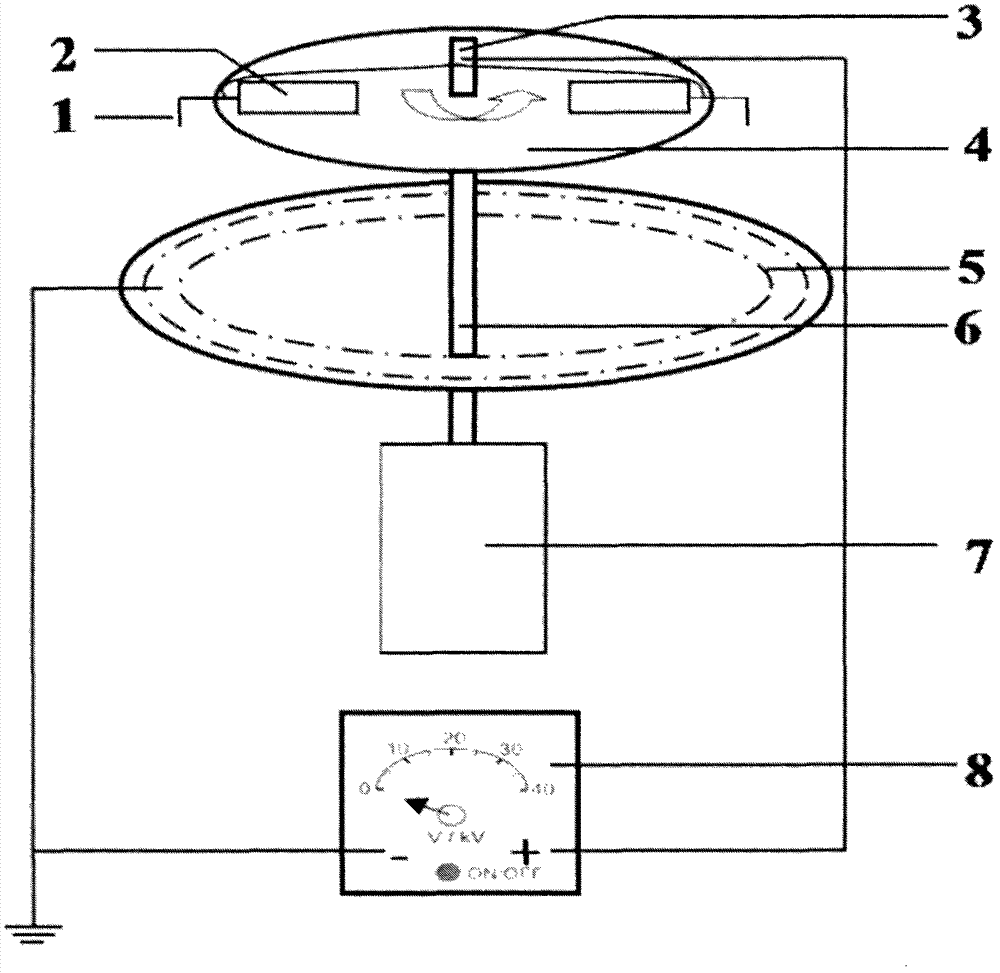
[0015] as attached figure 1 As shown, the positive pole of the high-voltage DC power supply 8 is connected to the metal rod 3, the negative pole is connected to the ring-shaped aluminum foil collecting pole 5 and grounded, and the position of the spinning solution container or the syringe needle tube 2 on the insulating rotating disk 4 is adjusted so that the tip of the spinning nozzle 1 and the The horizontal distance of the metal rod 3 is 15cm; the vertical distance between the tip of the spinning nozzle 1 and the annular aluminum foil collector 5 is 2-3cm, and the spinning solution is injected into the spinning solution container (syringe needle) 2; 8. Insert the plug into the daily 220V power supply, adjust the voltage adjustment knob on the voltage control panel, set the voltage to 2.5-5kV, and press the power switch to make it in the power-on state. At this time, the spinning nozzle 1 is supplied with high voltage...

Embodiment 2

[0016] Example 2: Preparation of nanofiber stranded wire structure.

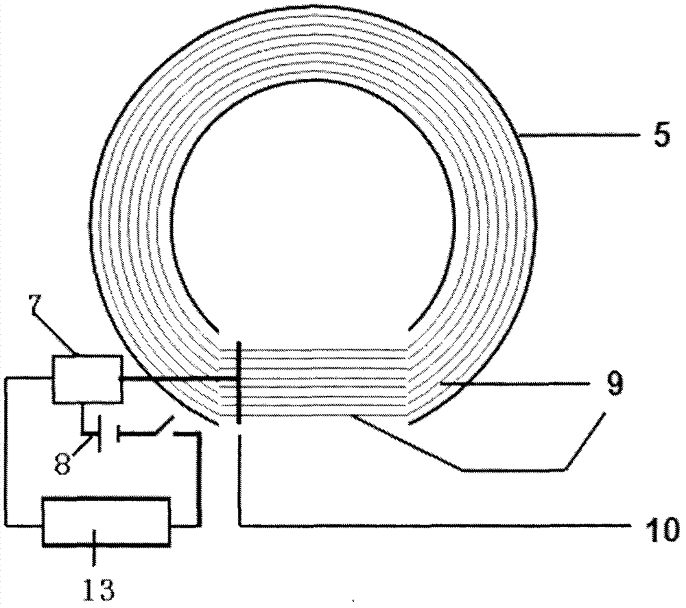
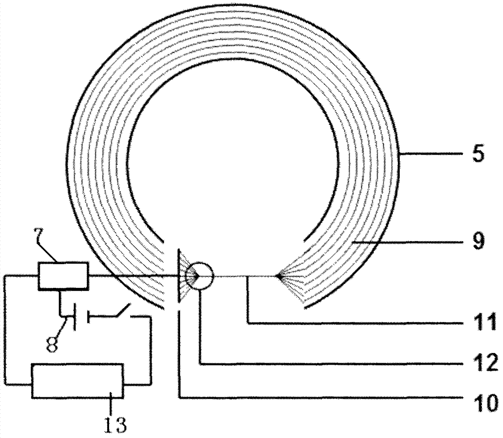
[0017] as attached figure 2 As shown, the spun fibers 9 arranged in an orderly manner are formed on the annular aluminum foil collector 5 by the centrifugal electrospinning method, and at the same time, the gaps of the annular aluminum foil collector 5 are formed to adhere to the T-shaped support 10. An orderly arrangement of overlapping structures. Use a thin rod to remove the fibers with poor shape and too close to the two ends of the T-shaped bracket 10, and cut off the fibers between the T-shaped bracket 10 and the aluminum foil near it, adjust the voltage of the speed regulator to the minimum, and open the Motor switch, adjust the speed to make the motor transition from slow to fast as much as possible, and a stranded wire structure will be formed after 5-60 minutes; if attached image 3 As shown, the nanofiber strand structure 11 and the umbrella structure 12 are held up by a glass slide from bottom...

Embodiment 3

[0019]In the device of this embodiment, 1.3 g of polymethylmethacrylate (polymethylmethacrylate, PMMA) was first dissolved in 8.7 g of N, N-dimethylformamide (N, N-dimethylformamide, DMF) with a mass ratio of 1:1 and tetrahydrofuran (tetrahydrofuran, THF) mixed solution, then add 0.026g fluorescein, stir with a magnetic stirrer for 2 hours, put it into the spinning solution container 2 after standing still for half an hour, and use centrifugal electrospinning method to obtain orderly For the fluorescent fibers that are connected, the DC brushless motor 7 is energized during the implementation process to allow the insulating rotating disk 4 to rotate at a speed of 360rpm, the distance between the spinning nozzle 1 and the annular aluminum foil collector 5 is 3cm, and the high-voltage DC power supply 8 The voltage is 3.5kV, disconnect the power supply 8 of the high-voltage electrostatic generator after 10s, turn off the brushless DC motor 7, remove the fibers with poor shape or t...


PUM

PropertyMeasurementUnit
tensile loadaaaaaaaaaa
diameteraaaaaaaaaa

Abstract

The invention belongs to the technical field of nano fiber twisted structure or micro-nano rope preparation, and particularly relates to a device for preparing a nano fiber twisted structure by using a centrifugal electrostatic spinning technology. A metal rod is placed in the vertical direction at the central line of an annular aluminum foil collector, a metal rod bracket passes through the center of the annular aluminum foil collector and is used for supporting and stabilizing the metal rod, and the bottom end of the metal rod is butted against and linked with the output shaft of a motor; and the upper part of the metal rod is provided with a circular insulated turntable vertical to the axis of the metal rod, two spinning solution containers are placed on the upper lateral surface of the insulated turntable and symmetrical to the central line of the metal rod, and the spinning solution containers are provided with communicated needle openings aligned with a spinning nozzle of the annular aluminum foil collector. The spun fiber number is accurate and controllable, the twisted structure is good, the lapping sequence is high, the voltage is low, burrs are not caused, and the deviceis convenient for measuring the mechanical property of single fibers.

Description

Technical field: [0001] The invention belongs to the technical field of nanofiber stranded wire structure or micro-nano rope preparation, and in particular relates to a device for preparing a nanofiber stranded wire structure by centrifugal electrostatic spinning technology. Background technique: [0002] Due to their small diameter and large specific surface area, quasi-one-dimensional nanofibers often exhibit physical and chemical properties different from those of bulk and thin film materials, such as light, electricity, magnetism, and force, and have broad application prospects. At present, the preparation methods involving nanofibers mainly include physical / chemical vapor deposition, template method, chemical self-assembly method and electrospinning method, etc. Among them, electrospinning is a simple and easy method that can be directly prepared from polymers and composite materials. The continuous fiber method has the outstanding advantages of low equipment and experi...

Claims


Application Information

Patent Timeline
Patent Type & Authority Patents(China)
IPC IPC(8): D01D5/00D01D5/18D01D13/00
Inventor 龙云泽尹红星刘术亮赵南赵志立唐成春
Owner QINGDAO UNIV
Why Eureka
Try Eureka