Internal combustion engine with thermoelectric generator

A technology for internal combustion engines and thermoelectric generators, applied in the direction of generators/motors, internal combustion piston engines, combustion engines, etc., can solve the problems of small power output, and achieve the effects of saving space, reducing friction, and fast and powerful heating

Inactive Publication Date: 2011-10-12
FORD GLOBAL TECH LLC
View PDF5 Cites 0 Cited by
  • Summary
  • Abstract
  • Description
  • Claims
  • Application Information

AI Technical Summary

Problems solved by technology

[0004] Despite the relatively high efficiency of thermoelectric generators according to the latest state of the art, known devices for energy recovery produce a rather small electrical output from exhaust heat

Method used


Image

  • Internal combustion engine with thermoelectric generator
  • Internal combustion engine with thermoelectric generator
  • Internal combustion engine with thermoelectric generator

Examples


Embodiment Construction

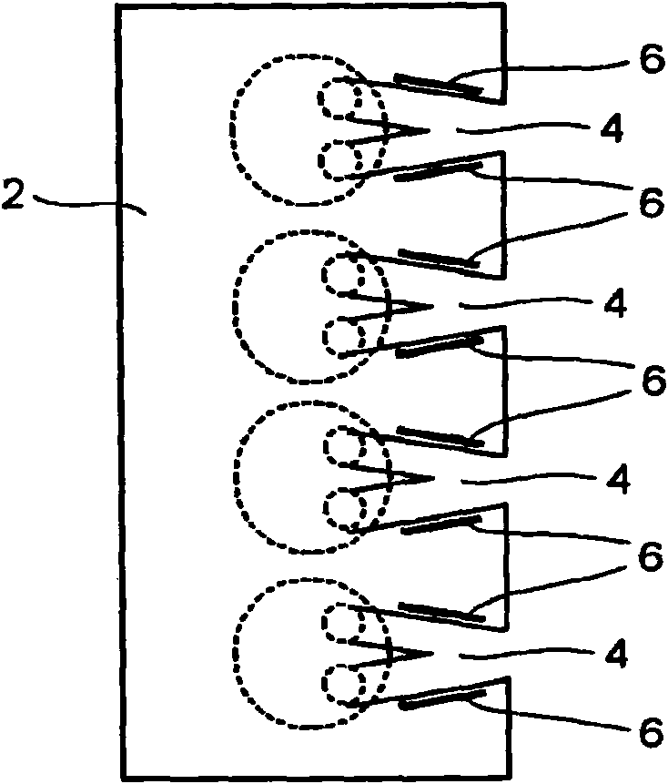
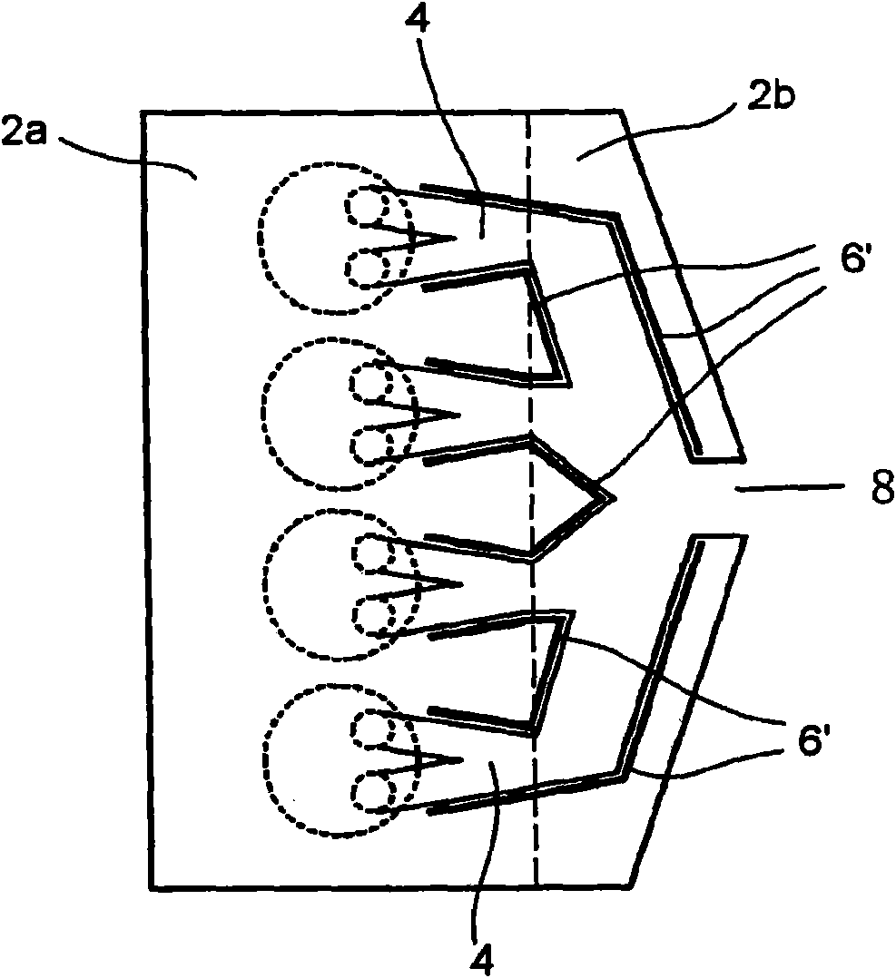
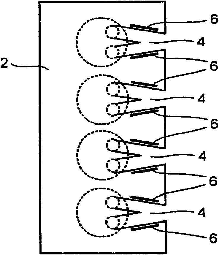
[0017] exist figure 1 In the cylinder head 2 shown, four cylinders and two exhaust valve openings in each cylinder are shown. At the start of the exhaust valve openings of each cylinder are exhaust ducts 4 converging in a V-shape, each V opening separately at the edge of the cylinder head 2 to a common row screwed to the cylinder head 2 gas collector (not shown).

[0018] A thermoelectric element 6 is arranged on the periphery of the exhaust duct 4 and is depicted with a thicker line, the thermoelectric element 6 being in thermal contact with the exhaust gas flowing through the exhaust duct 4 on the heat supply side and in thermal contact with the exhaust gas flowing through the cylinder head on the heat dissipation side. The coolant channels (not shown) in 2 are in thermal contact with the liquid coolant. In either case, there may be direct thermal contact or indirect thermal contact, for example via the metal of the cylinder head 2 , between the thermoelectric element 6 an...


PUM


Abstract

The invention relates to an internal combustion engine with one or more thermoelectric generators (6). The thermoelectric generator generates the current by a temperature difference between the exhaust of the internal combustion engine and a coolant. According to the invention, at least a thermoelectric generator is in thermal contact with an exhaust duct section (4) of the internal combustion engine near a combustion chamber at a heat supply side and is in thermal contact with the coolant for cooling the internal combustion engine and / or a heat conductive member of a cylinder cover (2) at a heat radiation side.

Description

technical field [0001] The invention relates to an internal combustion engine having one or more thermoelectric generators, according to the description of the present specification, which generate an electric current through the temperature difference between the exhaust gas of the internal combustion engine and the coolant. Background technique [0002] One type of internal combustion engine is known, for example, from DE 100 41 955 A1. In this publication, the temperature difference between the exhaust gas and the environment is used to generate an electrical current through a thermoelectric element utilizing the Seebeck effect. The thermoelectric elements may be formed along the entire length of the exhaust pipe or on sections of said exhaust pipe. With thermoelectric elements of this type, the inverse Seebeck effect, the Peltier effect, can also be used to heat components of internal combustion engines. [0003] US 2003 / 0223919 A1 discloses liquid cooling of a thermoe...

Claims


Application Information

Patent Timeline
Patent Type & Authority Applications(China)
IPC IPC(8): F01N5/02F01N13/08F02F1/24H02N11/00
CPCF01N5/025F01N13/102F02F1/40F02G5/02F02G2260/00Y02B30/52Y02T10/12
Inventor K·库尔贝奇
Owner FORD GLOBAL TECH LLC
Why Eureka
Try Eureka