Smoke exhaust system for realizing energy conservation by using coal-fired boiler flue-gas waste heat recovery and water conservation by using wet desulphurization

A waste heat recovery and wet desulfurization technology, applied in combustion methods, lighting and heating equipment, indirect carbon dioxide emission reduction, etc., can solve the problems of large consumption of high-quality heat energy, high auxiliary steam parameters, increased water evaporation, etc., to achieve energy saving Significant water energy saving, reduced water evaporation consumption, and reduced flue gas temperature

Inactive Publication Date: 2011-10-12
华润电力投资有限公司
View PDF4 Cites 13 Cited by
  • Summary
  • Abstract
  • Description
  • Claims
  • Application Information

AI Technical Summary

Problems solved by technology

[0003] For boiler flue gas desulfurization, the mature limestone gypsum wet desulfurization process (completed in the desulfurization tower 104) is generally used. This desulfurization process is mature. Compared with other desulfurization processes, it has high desulfurization efficiency, reliable system operation, and low cost. advantages, so it is widely used; however, the limestone gypsum wet desulfurization process requires water consumption. When the boiler exhaust gas temperature is high, the evaporation of water increases, resulting in a great waste of water resources
[0004] In addition, traditionally, coal-fired thermal boilers in power plants in the northern region generally use auxiliary steam to heat the boiler heater. Due to the high parameters of the auxiliary steam, it needs to consume a large amount of high-quality heat energy when used to heat the boiler heater. huge waste of energy

Method used


Image

  • Smoke exhaust system for realizing energy conservation by using coal-fired boiler flue-gas waste heat recovery and water conservation by using wet desulphurization
  • Smoke exhaust system for realizing energy conservation by using coal-fired boiler flue-gas waste heat recovery and water conservation by using wet desulphurization
  • Smoke exhaust system for realizing energy conservation by using coal-fired boiler flue-gas waste heat recovery and water conservation by using wet desulphurization

Examples


Embodiment Construction

[0014] The boiler flue gas waste heat recovery energy-saving and wet desulfurization water-saving and smoke exhaust system of the present invention will be further described below in conjunction with the accompanying drawings.

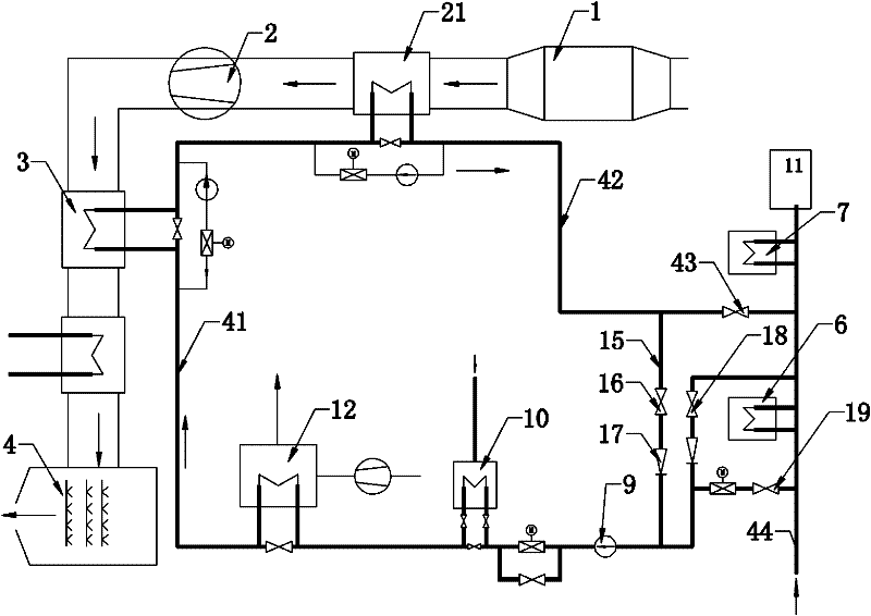
[0015] figure 2 It is the principle diagram of the first embodiment of the boiler flue gas waste heat recovery energy-saving and wet desulfurization water-saving smoke exhaust system of the present invention. The first embodiment is aimed at boilers in power plants (or thermal power plants), using condensed water from steam turbines in power plants as smoke The medium for gas waste heat recovery includes dust collector 1, induced draft fan 2, flue gas heat exchanger 3, and desulfurization tower 4 connected in sequence. The outlet of the cooling pipeline of the heater 3 is connected to the condensed water outlet pipe 42, wherein the flue between the dust collector 1 and the induced draft fan 2 is also provided with a secondary flue gas heat exchanger 2...


PUM


Abstract

The invention provides a smoke exhaust system for realizing energy conservation by using coal-fired boiler flue-gas waste heat recovery and water conservation by using wet desulphurization, wherein a secondary flue-gas heat exchanger is arranged between a dust collector and an induced draft fan, a cooling pipe of the secondary flue-gas heat exchanger is connected with a condensation water outlet pipe; a condensation water inlet pipe is provided with a boiler air heater, an auxiliary heater and a variable frequency boosted water pump which are connected in sequence from left to right, a startup bypass pipeline is arranged between the right side of the variable frequency boosted water pump and the far right end of the condensation water outlet pipe, a valve is arranged on the startup bypass pipeline and a check valve is arranged on the lower side of the valve. The smoke exhaust system for realizing energy conservation by using coal-fired boiler flue-gas waste heat recovery and water conservation by using wet desulphurization provided by the invention reduces the heat losses of smoke exhaust of the boiler, and the condensation water (or closed circulating water), instead of an auxiliary steam, is used to heat the boiler air heater, thus realizing energy conservation; meanwhile, as the temperature of smoke exhaust of the boiler decreases, the temperature of the smoke entering a desulphurization tower can be decreased, and the consumption of water evaporation in the desulphurization tower can be reduced.

Description

technical field [0001] The invention relates to a thermal boiler smoke exhaust system, in particular to a boiler flue gas waste heat recovery energy-saving and wet desulfurization water-saving smoke exhaust system. Background technique [0002] like figure 1 As shown, the smoke exhaust system of a coal-fired thermal boiler includes a dust collector 101 , an induced draft fan 102 , a flue gas heat exchanger 103 , and a desulfurization tower 104 connected in sequence. The inlet of the cooling pipeline of the flue gas heat exchanger 103 is connected to the condensed water inlet pipe 141, the outlet of the cooling pipeline of the flue gas heat exchanger 103 is connected to the condensed water outlet pipe 142, and the cooling in the cooling pipeline of the flue gas heat exchanger 103 The medium is the condensed water of the steam turbine. The condensed water inlet pipe 141 is connected to the condensed water outlet 144 of the steam turbine, and the rightmost end of the condense...

Claims


Application Information

Patent Timeline
Patent Type & Authority Applications(China)
IPC IPC(8): F23J15/04F23J15/06F23L15/00
CPCY02E20/34
Inventor 李曙光申焕民付京朝
Owner 华润电力投资有限公司
Why Eureka
Try Eureka