Valve rod automatic machining machine

An automatic processing and valve stem technology, which is applied in the direction of metal processing machinery parts, metal processing equipment, manufacturing tools, etc., can solve the problems of high processing cost, low processing precision, low processing efficiency, etc., and achieve consistent processing quality and low processing cost , high processing efficiency

Active Publication Date: 2012-12-26
ZHEJIANG ZHIYUAN VALVE TECH CO LTD
View PDF0 Cites 0 Cited by
  • Summary
  • Abstract
  • Description
  • Claims
  • Application Information

AI Technical Summary

Problems solved by technology

[0002] The processing procedure of the valve stem generally includes: forging forming → external cutting at both ends → cold extrusion thread. At present, the external cutting of both ends of the valve stem is generally processed by ordinary machine tools. A machine tool requires a skilled worker to operate, and the loading and unloading of the workpiece Both require manual operation, and the cutting accuracy of the workpiece is manually controlled by the operator, which has low processing efficiency, poor uniformity of workpiece processing size, and low processing accuracy.
However, the price of CNC machine tools is expensive, the processing cost is high, the level of operators is high, and the processing efficiency is not high enough.

Method used


Image

  • Valve rod automatic machining machine
  • Valve rod automatic machining machine
  • Valve rod automatic machining machine

Examples


Embodiment Construction

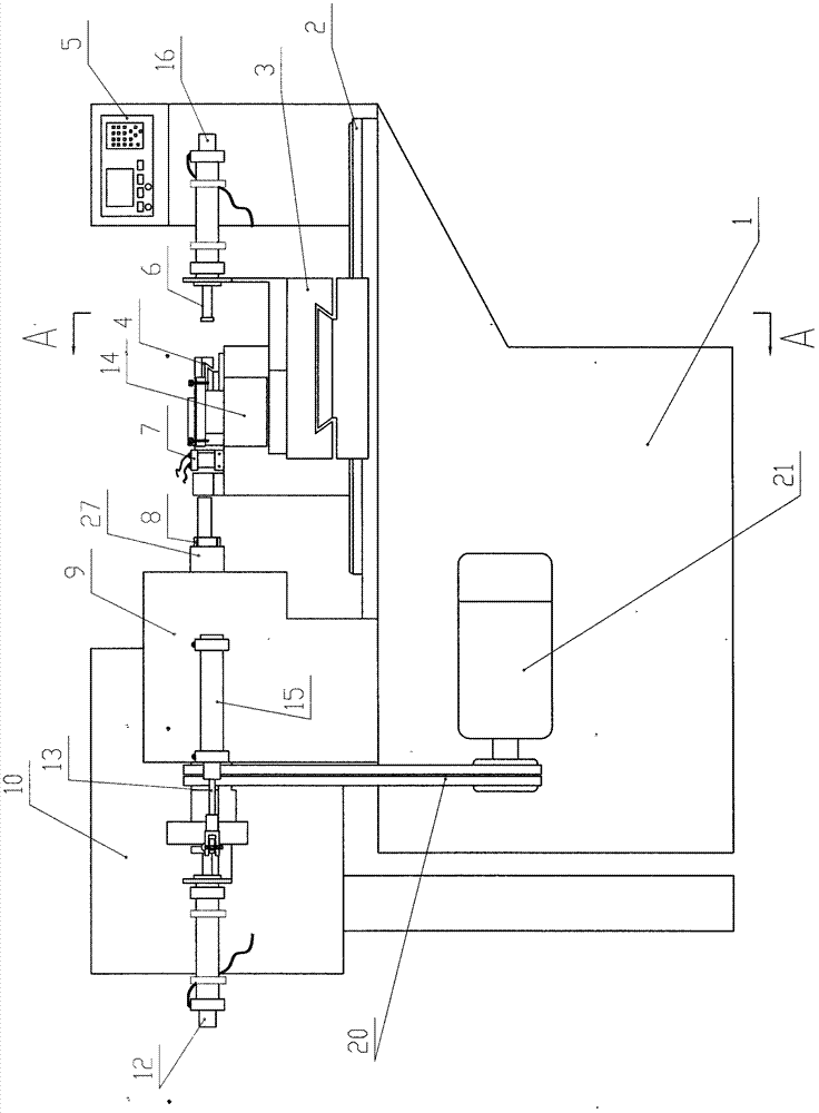
[0013] Such as figure 1 The valve stem automatic processing machine shown includes a main frame 1, a tool holder 14, a horizontal carriage 2, a longitudinal carriage 3, a headstock 9, a main shaft 27, a collet 8, a motor 21, and a tail box. The main shaft 27 is installed on the main shaft In the box 9, the rotating shaft of the motor 21 is connected with the belt 20, and the knife rest 14 is installed on the main frame 1 through the horizontal carriage 2 and the longitudinal carriage 3.

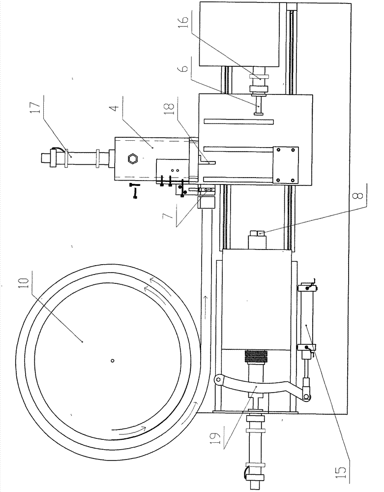
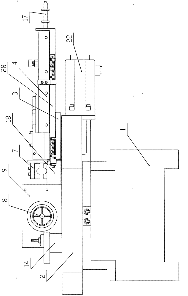
[0014] An automatic feeding device is provided on the main machine platform 1 opposite to the knife rest 14. The automatic feeding device is composed of a material conveying tray 10, a secondary longitudinal carriage 4, a pneumatic manipulator 7 and a limit block 18. The auxiliary longitudinal carriage 4 The pallet 28 is fixedly mounted on the main frame 1, the pneumatic manipulator 7 is fixedly mounted on the secondary longitudinal pallet 4, the limit block 18 is fixedly mounted on the palle...


PUM


Abstract

The invention relates to a valve rod automatic machining machine. The valve rod automatic machining machine comprises a main machine bench, a tool post, a cross slide, a longitudinal slide, a chuck, an electric motor and a tail box and is mainly characterized in that the main machine bench is provided with an automatic feeding device; the automatic feeding device consists of a material conveying disk, an auxiliary longitudinal slide, a pneumatic manipulator and a limited block; the auxiliary longitudinal slide is connected with a feeding air cylinder; the limited block is provided with a first sensor; the piston rod of the feeding air cylinder is provided with a second sensor; the tail box is provided with an ejecting air cylinder; the chuck is connected with an automatic clamping device and an automatic discharging device; the piston rod of the ejecting air cylinder is provided with a third sensor; the tail part of the main machine bench is provided with a computer control device; the positions of all the signal sensors are set according to the size of a valve rod; and the full-automatic valve rod machining from automatic feeding, automatic clamping, automatic cutting to automatic discharging is realized by using the computer control device. The valve rod automatic machining machine has the advantages of high machining efficiency, consistent machining quality, high machining accuracy, low machining cost and the like and is suitable for automatic machining equipment of the valve rod of a multi-turn valve.

Description

technical field [0001] The invention relates to a machining equipment, in particular to a valve stem cutting equipment. The invention is used for cutting the outer circle at both ends of the valve stem. Background technique [0002] The processing procedure of the valve stem generally includes: forging forming → external cutting at both ends → cold extrusion thread. At present, the external cutting of both ends of the valve stem is generally processed by ordinary machine tools. A machine tool requires a skilled worker to operate, and the loading and unloading of the workpiece Both require manual operation, and the cutting accuracy of the workpiece is manually controlled by the operator, which has low processing efficiency, poor uniformity of workpiece processing size, and low processing accuracy. However, the price of CNC machine tools is expensive, the processing cost is high, the level of operators is high, and the processing efficiency is not high enough. Contents of t...

Claims


Application Information

Patent Timeline
Patent Type & Authority Patents(China)
IPC IPC(8): B23B5/08B23Q3/06B23B15/00
Inventor 胡建华朱志远朱蔓茹吕加达苏佳佳朱胜若
Owner ZHEJIANG ZHIYUAN VALVE TECH CO LTD
Why Eureka
Try Eureka