
Hydraulic control system for rotation system of horizontal directional drilling machine

A technology of hydraulic control system and horizontal directional drilling rig, which is applied to the automatic control system of drilling, rotary drilling, rotary drilling rig, etc., can solve the problems of insufficient power, suction of hydraulic motor, excessive pressure loss of manual slide valve, etc. , to achieve the effect of convenient operation, small pressure loss and solving power shortage

Active Publication Date: 2011-10-19
南通堂润机械有限公司
View PDF7 Cites 9 Cited by
  • Summary
  • Abstract
  • Description
  • Claims
  • Application Information

AI Technical Summary

Problems solved by technology

[0003] The hydraulic system of the power head mostly uses a large-displacement main pump. If the manual spool valve is used to change the direction to realize the different flow collection and distribution methods of the hydraulic oil circuit, excessive pressure loss will be generated at the oil port of the manual spool valve. , resulting in insufficient power or hydraulic motor sucking air, etc.

Method used


Image

  • Hydraulic control system for rotation system of horizontal directional drilling machine
  • Hydraulic control system for rotation system of horizontal directional drilling machine
  • Hydraulic control system for rotation system of horizontal directional drilling machine

Examples


Embodiment Construction

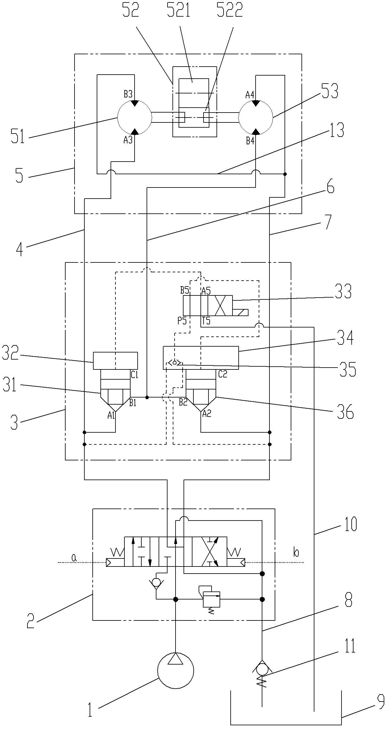
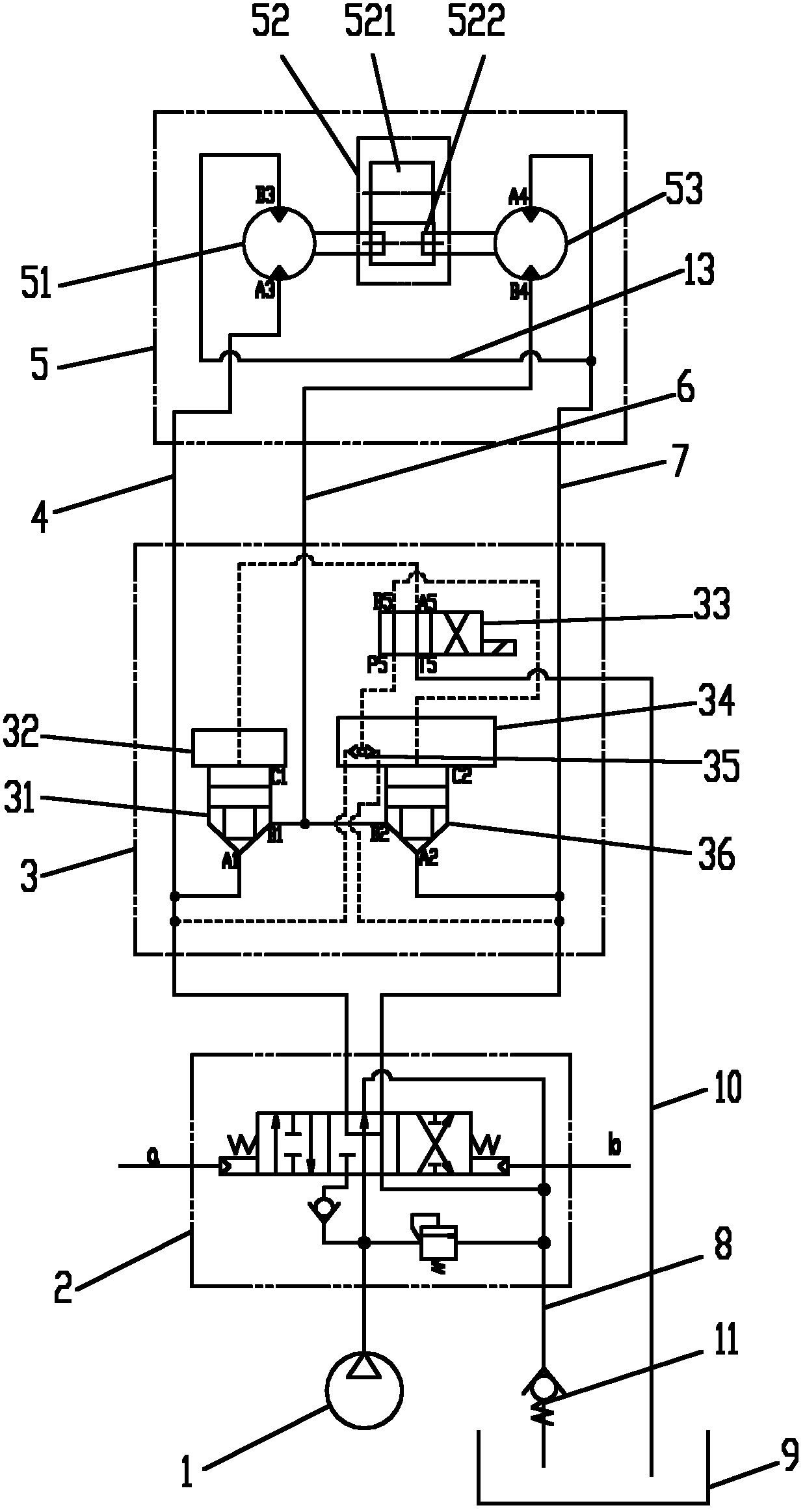
[0019] Such as figure 2 As shown, the hydraulic control system of the rotary system of the horizontal directional drilling rig of the present invention includes a main pump 1 , a main control valve 2 , a two-speed valve device, and a power head assembly 5 . (In order to distinguish the oil port or oil passage of each component, in this embodiment, numbers are added after the code of the corresponding oil port or oil passage for distinction.)

[0020] The power head assembly 5 mainly includes the hydraulic motor I53, the hydraulic motor II51 and the reducer assembly. The reducer assembly mainly includes the input gear 522 and the output gear 521. The output shafts of the hydraulic motor I53 and the hydraulic motor II51 are connected in series through the input gear 522. After the hydraulic motor I 53 and the hydraulic motor II 51 rotate, they drive the input gear 522 to rotate, and the input gear 522 drives the output gear 521 to complete the final rotation of the power head. ...


PUM


Abstract

The invention discloses a hydraulic control system for a rotation system of a horizontal directional drilling machine, and relates to a hydraulic control system for the horizontal directional drilling machine. The hydraulic control system comprises a main pump, a main control valve, a double-speed valve device and a power head assembly, wherein the double-speed valve device comprises a two-way cartridge valve I, a two-way cartridge valve II, a control cover plate I, a control cover plate II, an electromagnetic reversing valve and a shuttle valve; and a pressure signal of an oil circuit with higher pressure in an oil circuit I and an oil circuit III is introduced into the electromagnetic reversing valve through the shuttle valve, and is selectively introduced into a control cavity of the two-way cartridge valve I or the two-way cartridge valve II through different working positions of the electromagnetic reversing valve, the two-way cartridge valve with the pressure signal is in a closed state, and the two-way cartridge valve without the pressure signal is in an open state, so that an oil circuit II is selectively connected with the oil circuit I or the oil circuit II, different oil circuit connection modes are realized, the aim that the flow of the main pump is only supplied to a hydraulic motor I or is supplied to the hydraulic motor I and a hydraulic motor II simultaneously is fulfilled, and the rotation system of the drilling machine is switched between a high speed gear and a low speed gear.

Description

technical field [0001] The invention relates to a hydraulic control system of a horizontal directional drilling rig, in particular to a hydraulic control system of a rotation system of a horizontal directional drilling rig. Background technique [0002] For horizontal directional drilling rigs with constant pump hydraulic system, the rotation of the power head is generally driven by several hydraulic motors together with the reducer, and the reducer outputs power. Through different hydraulic oil circuit connection methods, two gears, high speed and low speed, can be realized. The high speed gear realizes high speed and low torque, and the low speed gear realizes low speed and high torque. Generally, through the reversing of the manual slide valve, the flow collection and distribution methods of different hydraulic oil circuits are realized, and several hydraulic motors are connected in series or in parallel to realize the switching between high and low gears. Such as figur...

Claims


Application Information

Patent Timeline
IPC IPC(8): E21B44/00F15B15/18E21B3/02
Inventor 玉有恩莫秀荣周旭明
Owner 南通堂润机械有限公司
Features
  • Generate Ideas
  • Intellectual Property
  • Life Sciences
  • Materials
  • Tech Scout
  • Unparalleled Data Quality
  • Higher Quality Content
  • 60% Fewer Hallucinations
Learn More