
Air preheater arrangement structure of boiler

An air preheater and layout structure technology, applied in lighting and heating equipment, combustion methods, indirect carbon dioxide emission reduction, etc., can solve the problems of coking in the combustion area, inability to solve the contradiction of boiler thermal efficiency in boiler drying treatment, and high demand for air temperature. Achieve the effect of less coking, solve the contradiction between boiler thermal efficiency and ensure normal combustion

Inactive Publication Date: 2011-10-19
WUXI HUAGUANG BOILER
View PDF4 Cites 5 Cited by
  • Summary
  • Abstract
  • Description
  • Claims
  • Application Information

AI Technical Summary

Problems solved by technology

[0003] The existing air preheater layout structure converts cold air into hot air, and both the primary air and secondary air flow out from the outlet of the air preheater. The air temperature of the two is almost the same, but in practice, the primary air is used Satisfy the drying treatment when the pulverizing system grinds lignite. The secondary air is used for combustion in the combustion area. The air temperature requirement of the primary air is higher than that of the secondary air. Once the air temperature of the secondary air is too high, it is easy to cause coking in the combustion area. , once the temperature of the primary air is too low, it is easy to cause poor drying treatment when the pulverizing system grinds lignite
To sum up, the existing air preheater layout structure cannot solve the contradiction between boiler drying treatment and boiler thermal efficiency

Method used


Image

  • Air preheater arrangement structure of boiler
  • Air preheater arrangement structure of boiler
  • Air preheater arrangement structure of boiler

Examples


Embodiment Construction

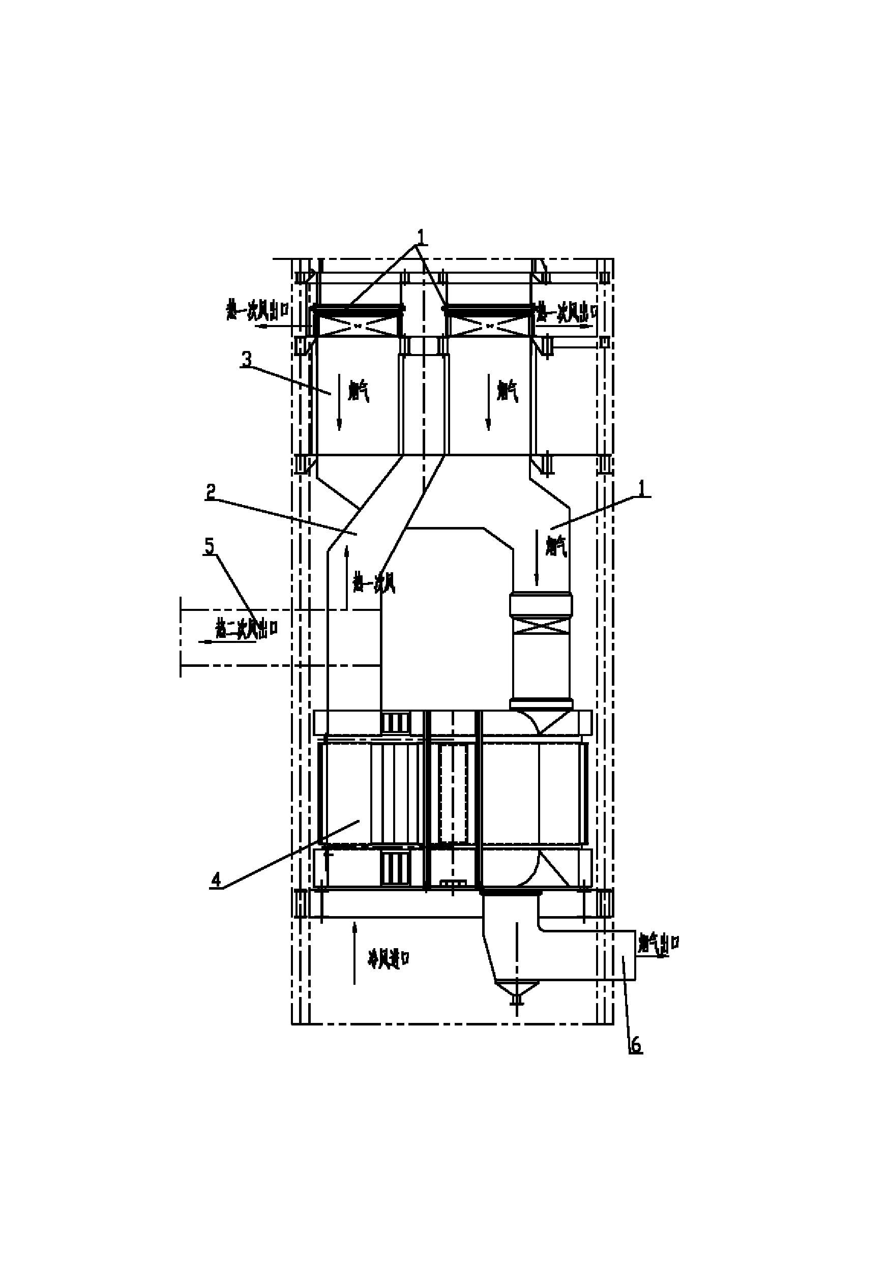
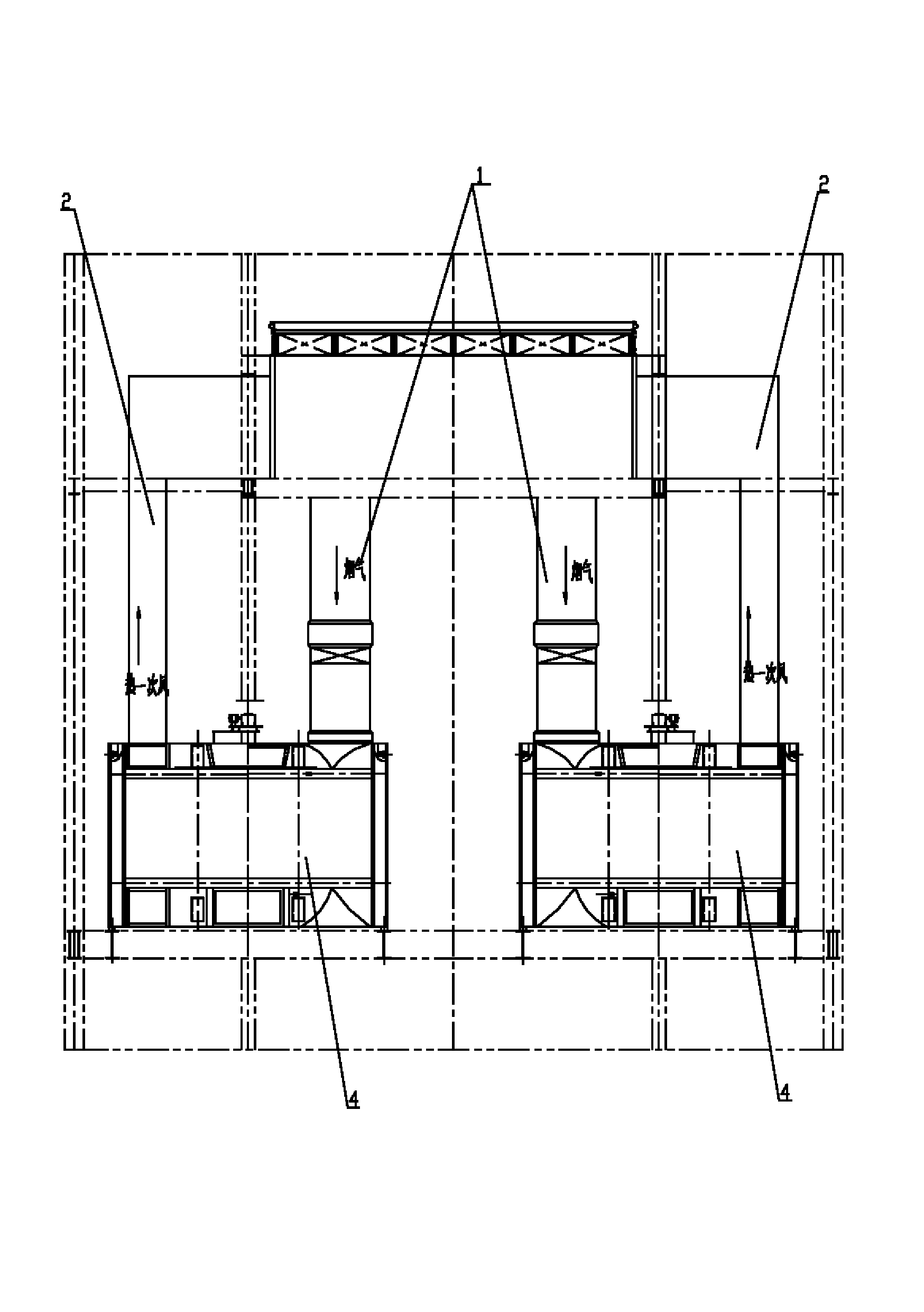
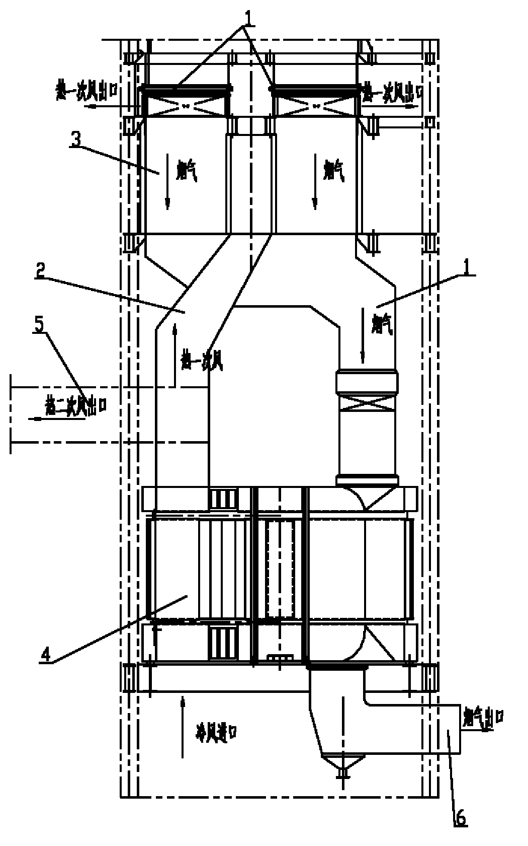
[0011] See figure 1 , figure 2 , which includes an air preheater, a flue 1, and a hot primary air duct 2. The air preheater includes a tubular air preheater 3 and a three-compartment rotary air preheater 4. The tubular air preheater 3 is located in Above the three-compartment rotary air preheater 4, the flue 1 runs through the tubular air preheater 3 and then connects to the flue gas inlet 4 of the three-compartment rotary air preheater, and the three-compartment rotary air preheater The inlet of 4 is connected to the cold air, and the air outlet of the three-part rotary air preheater 4 is connected to the air inlet of the tubular air preheater 3 through the hot primary air duct 2, and the middle part of the hot primary air duct 2 has secondary air The air outlet 5 and the secondary air outlet 5 are connected to the combustion area (not shown in the figure, which belongs to the existing mature structure), and the primary air outlet of the tubular air preheater 3 is connected...


PUM


Abstract

The invention provides an air preheater arrangement structure of a boiler, which can satisfy the requirements on drying process when a powder processing system grinds brown coal, and simultaneously can ensure normal combustion and less coking in a combustion zone, thereby further solving the contradiction between the boiler drying process and the thermal efficiency of the boiler. The air preheater arrangement structure comprises an air preheater, a flue and a hot primary air flue, and is characterized in that the air preheater comprises a tubular air preheater and a rotary air preheater, the tubular air preheater is arranged above the rotary air preheater, the flue penetrates through the tubular air preheater and then is connected with a smoke inlet of the rotary air preheater, an inlet of the rotary air preheater is communicated with cold air, an air outlet of the rotary air preheater is connected with an air inlet of the tubular air preheater by the hot primary air flue, a secondary air outlet is arranged in the middle of the hot primary air flue and is communicated with the combustion zone, and a primary air outlet of the tubular air preheater is communicated with a dying zone of the powder processing system for grounding the brown coal.

Description

technical field [0001] The invention relates to the technical field of boiler structure, in particular to the layout structure of the air preheater of the boiler. Background technique [0002] The air preheater is a gas-gas heat exchanger that uses the heat of flue gas to heat the air required for boiler combustion. It is an important and indispensable part of power plant boilers. The main function of the air preheater is to heat the air required for combustion and reduce the exhaust gas temperature of the boiler to improve the thermal efficiency of the boiler. [0003] The existing air preheater layout structure converts cold air into hot air, and both the primary air and secondary air flow out from the outlet of the air preheater. The air temperature of the two is almost the same, but in practice, the primary air is used Satisfy the drying treatment when the pulverizing system grinds lignite. The secondary air is used for combustion in the combustion area. The air tempera...

Claims


Application Information

Patent Timeline
IPC IPC(8): F23L15/00
CPCY02E20/34
Inventor 耿长萍韦志平何雁飞孟慧
Owner WUXI HUAGUANG BOILER
Learn More