Large-speed-difference flue gas circulation and ultralow nitrogen oxide high-speed burner and control method thereof

A flue gas circulation and nitrogen oxide technology, which is applied in combustion methods, furnace control devices, gas fuel burners, etc., can solve the problem of high emissions, and achieve the effect of reducing the calorific value of gas and reducing NOx emissions.

Pending Publication Date: 2020-07-28
WUHAN UNIV OF SCI & TECH
View PDF8 Cites 4 Cited by
  • Summary
  • Abstract
  • Description
  • Claims
  • Application Information

AI Technical Summary

Problems solved by technology

[0005] The purpose of the invention is in order to solve the combustion device NO of the metallurgical kiln existing in the prior art X Problem with high emissions, especially NO when using natural gas X To solve the problem of high emissions, provide a si

Method used


Image

  • Large-speed-difference flue gas circulation and ultralow nitrogen oxide high-speed burner and control method thereof

Examples


Example Embodiment

[0019] Embodiment 1: The present invention provides a high-speed flue gas circulating ultra-low NOx high-speed burner and its control method. The high-speed burner of this embodiment is used in a high-temperature tunnel annealing furnace for oriented silicon steel, using natural gas as fuel. The maximum furnace temperature of the annealing furnace reaches 1320°C.

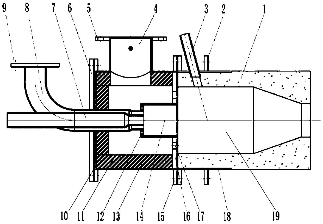
[0020] The structure of this high-speed burner is as follows figure 1 As shown, there are burner brick 1, burner mounting flange 2, ignition gun tube 3, air inlet pipe 4, air inlet pipe flange 5, fixed inlet pipe flange 6, gas inlet pipe 7, circulating flue gas inlet Air pipe 8, circulating flue gas inlet pipe flange 9, burner shell flange A10, burner shell 11, pre-combustion chamber 14, burner shell flange B15, air distribution plate 16 and burner brick outer cylinder 18 The inner cavity of the burner brick 1 is used as the combustion chamber 19, the outer cylinder of the burner brick wraps the rear of the burner bric...

Example Embodiment

[0028] Embodiment 2: The present invention provides a high-speed flue gas circulating ultra-low nitrogen oxide high-speed burner and its control method. The high-speed burner of this embodiment is used for seamless steel pipe heating. deal with Furnace, using coke oven gas as fuel deal with The maximum furnace temperature of the furnace reaches 1050°C.

[0029] The structure of the high-speed burner is the same as that of Example 1, except that the control method of the burner is used. When the furnace temperature is lower than 900°C, 26% of the combustion-supporting air in the burner shell enters through the primary air inlet channel 12 The pre-combustion chamber 14 and the coke oven gas entering through the gas inlet pipe 7 reach the pre-combustion chamber for pre-mixing and combustion. The incompletely combusted high-temperature flue gas produced after combustion is ejected into the burner brick at a flow rate of 2-5m / s In the combustion chamber 19 of the inner cavity, the ...


PUM


Abstract

The invention relates to a large-speed-difference flue gas circulation and ultralow nitrogen oxide high-speed burner and a control method thereof. The burner is provided with a burner brick, an air, fuel gas and circulating flue gas inlet tube, a burner housing and a pre-combustion chamber, wherein the inner cavity of the burner brick is a combustion chamber; a fuel gas inlet end of the pre-combustion chamber is provided with a primary air inlet channel; the outlet of the pre-combustion chamber is provided with an air distributing disc; and a secondary air inlet channel is arranged on the airdistributing disc. While the burner works, fuel gas and flue gas is pre-mixed and combusted in the pre-combustion chamber. Through a two-stage air distribution way, a gas mixture sprayed out by the pre-combustion chamber and flow speed of combustion-supporting air sprayed out through the secondary air inlet channel define large speed difference, so that an air flow reflow region is made in the outlet area of the pre-combustion chamber; and the airflow reflow region guarantees stable fuel gas and complete combustion in a furnace kiln. According to the control method, circulating flue gas is notinput into the burner while the furnace temperature is lower than a temperature of 900 DEG C, circulating flue gas is input into the burner to participate in combustion while the furnace temperatureis higher than the temperature of 900 DEG C, the circulating flue gas reduces a fuel gas heat value and a high temperature point of combustion flames, and ultralow NOX emission is realized.

Description

technical field [0001] The present invention relates to a high-speed burner with large speed difference flue gas circulation and ultra-low nitrogen oxides and its control method, in particular to a combustion device and its control technology for metallurgical kilns using gas as fuel, such as A high-velocity difference flue gas circulation ultra-low nitrogen oxide high-speed burner used in heat treatment furnaces, heating furnaces and other combustion devices and a control method thereof. Background technique [0002] my country's nitrogen oxide emission standards for the iron and steel industry are becoming increasingly stringent, requiring new (including relocated) iron and steel projects across the country to reach ultra-low emission levels in principle, and at the same time vigorously promote the ultra-low emission transformation of existing iron and steel enterprises. At present, the heat treatment furnaces and heating furnaces in my country's metallurgical furnaces mai...

Claims


Application Information

Patent Timeline
IPC IPC(8): F23D14/48F23D14/02F23D14/66F23L9/00F27D17/00F27D19/00
CPCF23D14/48F23D14/02F23D14/66F23L9/00F27D17/008F27D19/00F27D2019/0003Y02E20/34
Inventor 戴方钦郭悦潘卢伟陈平安陆浩
Owner WUHAN UNIV OF SCI & TECH
Why Eureka
Try Eureka