Method for measuring thickness by pulse infrared thermal wave technology

A technology of infrared thermal wave and pulse heating, which is applied in the field of infrared thermal wave technology, can solve the problems of error, second-order differential peak time noise, and difficult to implement, etc., and achieve the effect of simple processing method

Active Publication Date: 2011-10-19
CAPITAL NORMAL UNIVERSITY +1
View PDF5 Cites 36 Cited by
  • Summary
  • Abstract
  • Description
  • Claims
  • Application Information

AI Technical Summary

Problems solved by technology

US5711603 uses the differential peak time of the defect area minus the reference area temperature curve as the characteristic time. This patent needs to select a reference area first, which is difficult to achieve in some applications and introduces errors
The contrast peak method uses the peak time of the temperature curve of the defect area minus the reference area as the characteristic time, but the peak time is greatly affected by factors such as the size of the defect, and the reference area is also required
S.M.Shepard uses the peak time of the second-order temperature-

Method used


Image

  • Method for measuring thickness by pulse infrared thermal wave technology
  • Method for measuring thickness by pulse infrared thermal wave technology
  • Method for measuring thickness by pulse infrared thermal wave technology

Examples


Embodiment Construction

[0022] In order to better understand the shape, structure and characteristics of the present invention, preferred embodiments will be listed below and described in detail with reference to the accompanying drawings.

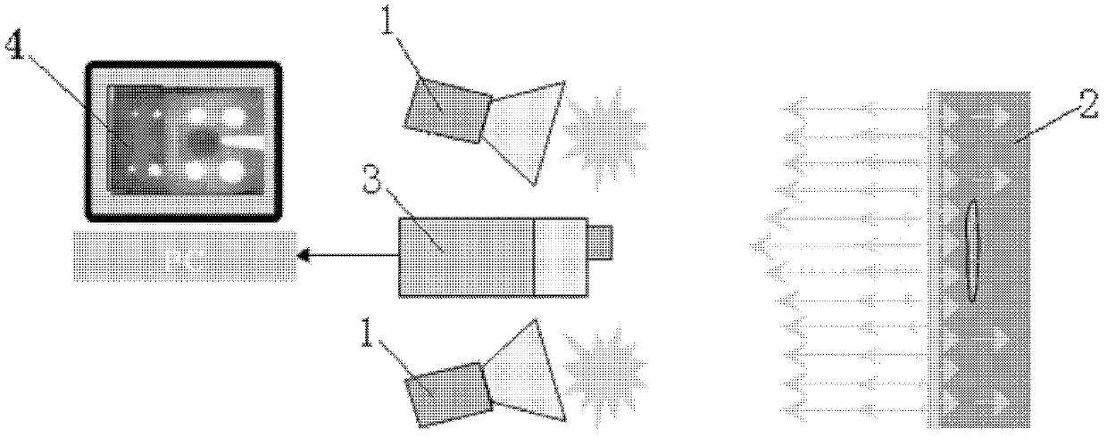
[0023] The theoretical basis of the present invention is based on the solution of the one-dimensional heat conduction equation under the excitation of a pulse plane heat source. For a semi-infinite homogeneous medium, when subjected to a uniform pulse heat source parallel to the surface of the medium, the heat conduction equation can be simplified as:

[0024]

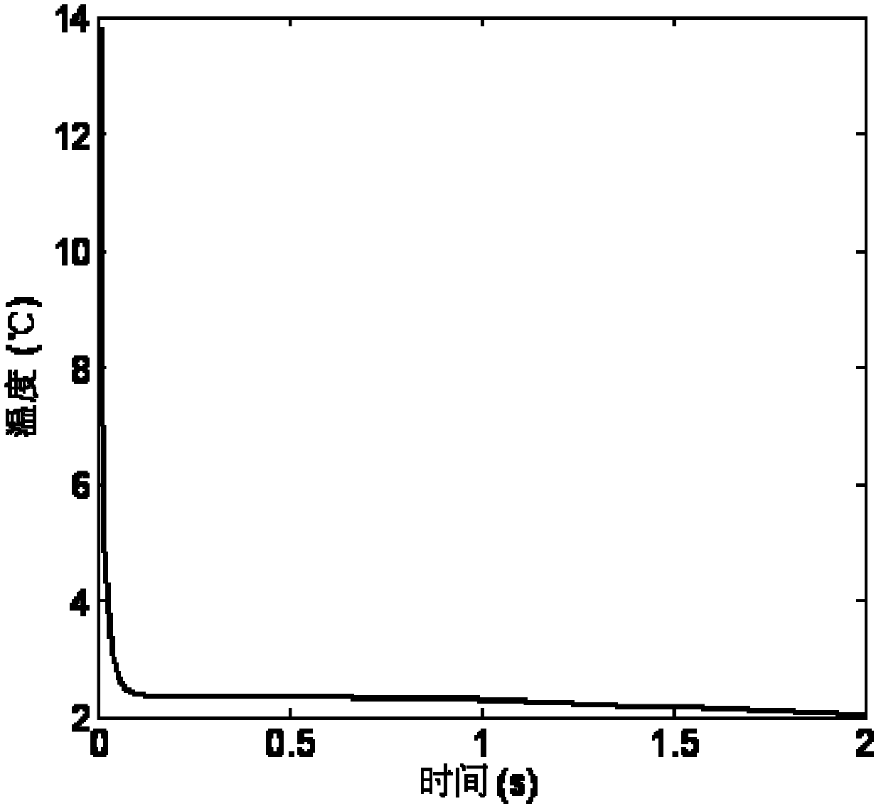
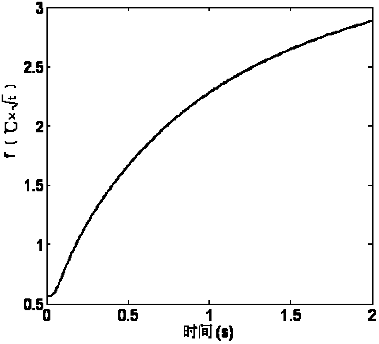
[0025] Among them, T(x, t) is the temperature at time t at x, qδ(t)δ(x) is the pulse heat source function, q is a constant, which is the heat applied on the unit area, k(W / m K) is the thermal conductivity. Density ρ(kg / m 3 ) and the product of the specific heat c is the bulk heat capacity of the dielectric material. The thermal diffusivity is α=k / (pc). For a certain medium, α can be regarded as a co...


PUM


Abstract

The invention provides a method for measuring thickness or defect depth by a pulse infrared thermal wave technology, comprising the following steps of (1) heating an object to be measured by pulse heating equipment; obtaining a thermographic sequence on the surface of the object to be measured by an infrared thermal imaging device; memorizing the thermographic sequence in a general memory; (2) multiplying a temperature-time curve of each point in the thermaographic sequence with corresponding time, thus obtaining a new curve f; (3) working out first-order differential on the f; and obtaining a peak time tapst; (4) working out L by a formula, wherein Alpha is thermal diffusion coefficient and L is the thickness or the defect depth of the object to be measured. By adopting the technical scheme, the thickness or detect depth of a part to be measured can be measured, a reference curve is not needed, and only one-order differential treatment is needed for the measurement, so that the processing method is simpler.

Description

technical field [0001] The invention relates to the technical field of non-destructive flaw detection, in particular to an infrared thermal wave technology, a method for measuring the thickness of a test piece or the depth of a defect by using the pulsed infrared thermal wave technology. Background technique [0002] Pulse infrared thermal wave non-destructive testing technology is a non-destructive testing technology developed after the 1980s. This method is based on thermal wave theory, by actively applying pulse thermal excitation to the measured object, and using infrared thermal imager to continuously observe and record the temperature field changes on the surface of the object, and through modern computer technology and image information processing technology. Detection, acquisition, data processing and analysis of time-series thermal wave signals to realize quantitative diagnosis of internal defects or damages of objects. [0003] The measurement of defect depth or t...

Claims


Application Information

Patent Timeline
IPC IPC(8): G01B11/06G01B11/22
CPCG01B21/085G01N25/72
Inventor 曾智王迅陶宁冯立春张存林
Owner CAPITAL NORMAL UNIVERSITY
Why Eureka
Try Eureka