Twin exhaust gas purifying tower

A purification tower and exhaust gas technology, applied in the separation of dispersed particles, chemical instruments and methods, separation methods, etc., can solve the problems of increased difficulty and cost of installation and maintenance, increased difficulty of operation and control, and high consumption of circulating washing kinetic energy, and can achieve installation and maintenance. And the effect of easy maintenance, reduced manufacturing cost and high utilization rate

Active Publication Date: 2011-10-26
永兴县皓天环保科技发展有限责任公司
View PDF4 Cites 7 Cited by
  • Summary
  • Abstract
  • Description
  • Claims
  • Application Information

AI Technical Summary

Problems solved by technology

Some special flue gas scrubbing, absorbing and purifying equipments have also been published in Chinese patents. These equipments are all single-tower structures, and the same mass transfer time is relatively high, and the inlet and outlet are located in the tower, which increases installation and maintenance. Difficulty and cost; the absorption method is mostly reverse, and the flow velocity in the empty tower is relatively low due to the limit of liquid flooding, generally less than 3 m / s, and the corresponding absorption tower diameter is too large; only one main circulation pool is equipped, which is used as a regeneration reaction pool It is also used as an oxidation reaction tank, which increases the difficulty of operation and control, reduces the utilization rate of the absorption medium, and at the same time, the solid content of the circulating liquid is seriously high, which increases the wear of the pump and nozzle; especially the amount of washing liquid used in circulation is large, The liquid-gas ratio is mostly 10-25L / m 3 ; The head is high, resulting in excessive consumption of cycle washing kinetic energy, and the total operating cost is obviously too high

Method used


Image

  • Twin exhaust gas purifying tower
  • Twin exhaust gas purifying tower

Examples


Embodiment Construction

[0014] The present invention will be further described below in conjunction with the accompanying drawings, and this embodiment does not constitute a limitation to the present invention.

[0015] The structure of twin exhaust gas purification towers of the present invention is:

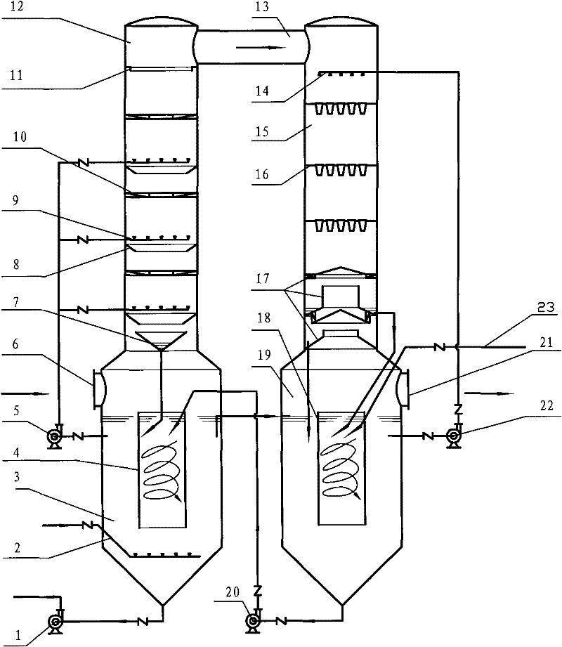
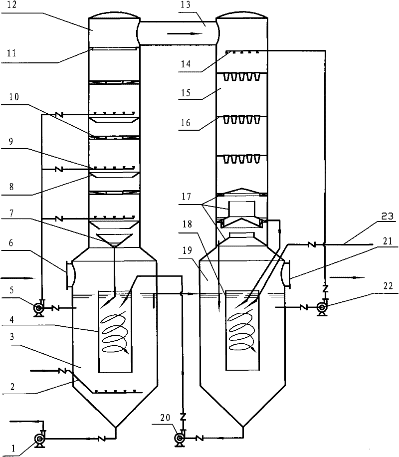
[0016] The twin exhaust gas purification towers as shown in the figure include parallel I towers 12, II towers 15, corresponding lower I tower circulation pools 3, II tower circulation pools 19, and connecting pipes 13 connected by the top two towers. In 12, the liquid collection bucket 7, the three-layer liquid guide ring 8, the three-layer nozzle 9, the three-layer swirl plate 10, and the top liquid ring 11 are respectively arranged from bottom to top, and the waste gas provided on the I tower circulation pool 3 Inlet 6, exhaust gas enters tower I from exhaust gas inlet 6, tower I spacer 4 is set in tower I circulation pool 3, air enters tower I from oxidation device 2, and tower cloth liquid II is ...


PUM


Abstract

The invention discloses a twin exhaust gas purifying tower, which comprises towers I and II and tower circulating pools I and II, wherein the towers I and II are paratactic and serially connected with each other; the circulating pools of the tower I and II are corresponding to the lower parts of the towers I and II; a liquid gathering hopper, a liquid-guiding ring, a nozzle, a spiral flow plate and a top liquid baffle ring are arranged in the tower I from bottom to top; an exhaust gas inlet and an air oxidation device are arranged on the tower I circulating pool; a tower II liquid distributing pipe, a conical cup atomizing layer and a multi-ring whirlwind demister are arranged on the tower II from top to bottom; a clean gas outlet is arranged on the tower II; spacing rings are arranged onthe circulating pools on the lower parts of the towers I and II; circulating pumps are arranged in the circulating pools of the tower I and II; lifting pumps and dewatering pumps are arranged at bottoms of the towers I and II; and a medium conveying pipe is arranged on the upper part of the tower II. By using the twin exhaust gas purifying tower, a gas/liquid mass transfer area is increased, a gas/liquid contact area is updated by repeatedly cutting, the purifying efficiency is high, the consumption of circulating kinetic energy is reduced, the flow speed of idle tower is increased, the reaction of absorbing medium is more complete, the utilization ratio is higher, solid content in cleaning solution in the towers is reduced, the abrasions of the circulating pumps and the nozzle are reduced, the service life is prolonged, and the maintenance is more convenient. The twin exhaust gas purifying tower is mainly used for cleaning, absorbing and purifying the exhaust gas.

Description

Technical field [0001] The invention relates to a flue gas desulfurization and purification equipment, specifically refers to using lime as a medium to wash and absorb SO 2 Twin waste gas purification towers for acid waste gas. Background technique [0002] Flue gas scrubbing, absorption and purification equipment is the most commonly used and most effective SO 2 Emission reduction equipment for acid waste gas. Commonly used technologies include spray tower, packed tower, liquid column tower, plate tower, and the double-loop tower adopted by the more advanced American NOELL-KRC process. Some special flue gas scrubbing, absorbing and purifying equipments have also been published in Chinese patents. These equipments are all single-tower structures, and the same mass transfer time is relatively high, and the inlet and outlet are located in the tower, which increases installation and maintenance. Difficulty and cost; the absorption method is mostly reverse, and the flow veloc...

Claims


Application Information

Patent Timeline
Patent Type & Authority Applications(China)
IPC IPC(8): B01D53/75B01D53/50
Inventor 陈曙平陈皓鋆
Owner 永兴县皓天环保科技发展有限责任公司
Why Eureka
Try Eureka