
Multistage series-connection gasifier chamber structure

A furnace structure and gasifier technology, which are used in the gasification of granular/powder fuel, the manufacture of combustible gas, the petroleum industry, etc. Problems such as low space utilization rate of gasification furnace

Inactive Publication Date: 2011-10-26
中国东方电气集团有限公司
View PDF4 Cites 6 Cited by
  • Summary
  • Abstract
  • Description
  • Claims
  • Application Information

AI Technical Summary

Problems solved by technology

For entrained bed gasifiers (including coal water slurry and dry pulverized coal gasifiers), during the coal gasification process, the gas flow rate will gradually increase as the reaction proceeds, and the furnace space of equal furnace diameter is not suitable for each gasification reaction. Step-by-step requirements are not conducive to the optimization of the reaction process; at the same time, due to the large volume of the front end of the reaction zone, it will cause a local high-temperature reflow zone in the front section of the reaction zone, resulting in low space utilization of the gasification furnace and increasing the possibility of vault collapse caused by high-temperature radiation sex
[0005] The above defects are all caused by the unreasonable layout of the existing entrained-flow gasifier furnace, and there will also be problems such as low carbon conversion rate, improper distribution of flow field and temperature field

Method used


Image

  • Multistage series-connection gasifier chamber structure
  • Multistage series-connection gasifier chamber structure

Examples


Embodiment Construction

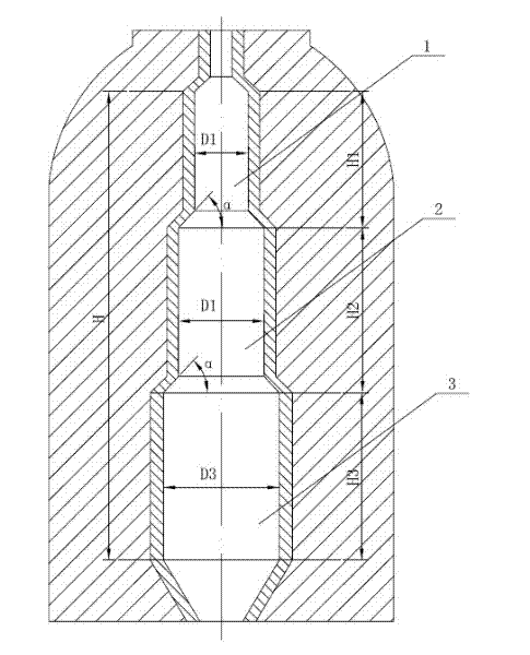
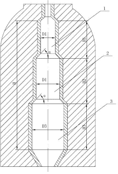
[0020] Such as figure 1 As shown, the furnace structure of the multi-stage series gasifier includes the first-stage furnace 1, the second-stage furnace 2 and the third-stage furnace 3 connected in sequence in the longitudinal direction, and the first-stage furnace 1, the second-stage furnace 2 and the third-stage furnace The three-stage furnaces 3 are all hollow cylinders, and the first-stage furnace 1, the second-stage furnace 2 and the third-stage furnace 3 are connected by a hollow frustum of cone.

[0021] The first-stage furnace 1 is located at the upper end with a diameter of D 1 , with height H 1 ;The second-stage furnace 2 is located in the middle, with a diameter of D 2 , with height H 2 ; The third stage furnace 3 is located at the lower end, with a diameter of D 3 , with height H 3 ; The total height of the three-stage furnace is H, that is, H=H 1 +H 2 +H 3 .

[0022] And the three-stage hearth is satisfied: D 1 2 3 , 01 2 3 <H.

[0023] The diameter D of...


PUM


Abstract

The invention relates to entrained flow gasifier technology, and particularly discloses a multistage series-connection gasifier chamber structure which comprises a first-stage chamber, a second-stage chamber and a third-stage chamber which are sequentially connected in the longitudinal direction, wherein the first-stage chamber, second-stage chamber and third-stage chamber are respectively a hollow cylinder and are connected through a hollow cone. By organizing the gasifier chambers in a multistage series-connection structure, the reaction regions in the chambers are distributed in a more reasonable way, thereby prolonging the retention time of coal powder particles in the reaction regions, increasing the carbon conversion rate, reducing the volume of the upper mixing region and pyrolysis region, reinforcing the mass transfer, reducing the high-temperature backflow region and lowering the possibility of vault slump.

Description

technical field [0001] The invention relates to the technology of an entrained bed gasification furnace, in particular to the furnace structure of a multi-stage serial gasification furnace. Background technique [0002] The entrained bed gasifier has the characteristics of strong adaptability to coal types, high degree of automation, stable and reliable operation, high gasification intensity, high gasification efficiency and simple treatment of three wastes. It is currently the mainstream gasifier type. [0003] At present, the entrained-flow gasifier can be divided into one-stage furnace and two-stage furnace according to the gasification space, and can be divided into coal-water slurry gasifier and dry coal powder gasifier according to the feed material, and can be divided into liquid gasifier according to the slagging method. Slagging and solid-state slagging gasifiers. [0004] The structures of the existing entrained-bed gasification furnaces are all single cylinders o...

Claims


Application Information

Patent Timeline
IPC IPC(8): C10J3/48C10J3/60
Inventor 曹立勇张庆王晓亮胡蕴成
Owner 中国东方电气集团有限公司
Learn More