Cutting head for high-speed lower-layer cutting bed

A cutting and low-level technology, applied in the cutting of textile materials, textiles and papermaking, etc., can solve the problems of increased energy consumption, low efficiency, high cost of use, etc., to achieve easy maintenance and repair, reduce manufacturing costs, and high mechanical reliability Effect

Active Publication Date: 2013-10-16
HANGZHOU ECHO SCI TECH
View PDF7 Cites 0 Cited by
  • Summary
  • Abstract
  • Description
  • Claims
  • Application Information

AI Technical Summary

Problems solved by technology

The existing so-called low-level cutting bed produced in China is simply to add a cutting knife to the paper pattern cutting machine, and the knife can be dropped at a fixed height through a servo motor. The fabric cannot be cut, especially the large-format fabric cutting, and the scope of use is limited. It cannot be applied to industries such as large toy inflatable models, membrane structures, and rowing shipbuilding industries that urgently need low-level cutting machines. Only small-format cutting can be performed. , has little practical significance, and is not a low-level cutting bed in the true sense.
Most of the cutting heads in foreign low-level cutting machines have single functions, fewer types of knives, and no red light preview function. Cutting different fabrics requires cumbersome tool changes and adjustments. It is easy to cut waste fabrics and waste fabrics. In addition, The pen used is also very special and cannot be replaced with an ordinary pen. After the ink is used up, it can only be replaced with a pen produced by a foreign original factory, which is very expensive to use
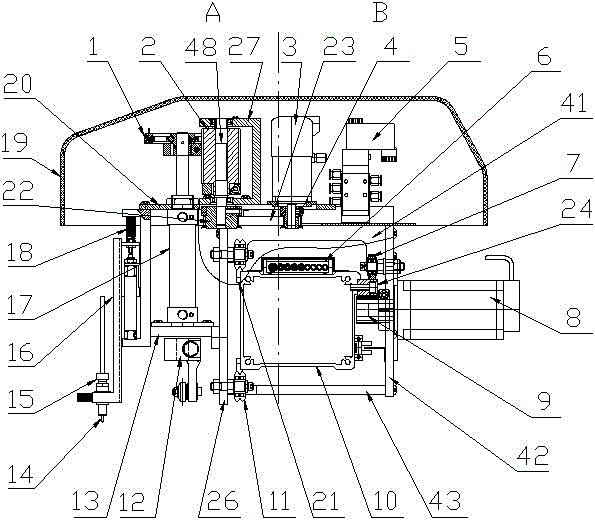
[0004] There are also some relatively good cutting heads used in the cutting bed at present, as disclosed on February 18, 2009, and the publication number is CN101367215 in the Chinese patent, which discloses a cutting head for high-speed low-level cutting bed The cutting head for high-speed low-level cutting machine includes cutting head frame, pen, flat knife, pointed knife, round knife and punching drill. The pen is set on the pen stand, which is connected to the vertical movement of the pen-down cylinder end, the fixed end of the pen-down cylinder is connected to the cutting head frame; The flat knife belt wheel on the cutting head frame is connected by splines; the sharp knife, round knife and flat knife are set in the same way; the punching drill is set on the output shaft of the punching air motor, and the punching air motor is set on the punching drill base. The punching drill base is fixedly connected to the vertical moving end of the punching cylinder, and the fixed end of the punching cylinder is connected to the cutting head frame; among them, each cylinder is connected with the solenoid valve, and each pulley is connected with the rotary knife servo motor. , the solenoid valve and rotary knife servo motor are set on the cutting head frame and connected with the control circuit; the structural design of the cutting head is not reasonable enough, the whole is not simple and light enough, and the cutting head is not accurate in the cutting process
Another example is that the publication date is July 7, 1998, and the publication number is US5775189A, which discloses a cutting machine. The cutting machine includes a cutting frame. The knives are all set on the lower end of the piston rod of the oil cylinder, the oil cylinder is fixed on the cutting frame, the upper end of the piston rod is connected with the pulley on the cutting frame, the cutting frame is equipped with a circular knife motor, an angular displacement servo motor and a cam motor, and the motor Both are connected to the control circuit; the structure of the cutting machine is relatively complicated, and the stability of the cutting machine in the cutting process is poor, resulting in relatively poor quality of the cut products
Another example is that the publication date is June 30, 2005, and the publication number is JP2005171420A Japanese Patent, which discloses a high-speed low-level cutting bed, which includes cutting heads, support tables, beams and other parts. A punching drill and a coloring pen are set on the top, the pen is arranged on the pen stand, the pen stand is connected to the vertical end of the first cylinder, and the fixed end of the cylinder is connected to the cutting head; the structural design of the cutting head on the cutting bed is not enough Reasonable, inconvenient to use, difficult to effectively improve the accuracy of cutting
In addition, if the publication date is July 11, 2007, the publication number is CN1994695A in the Chinese patent, which discloses a multifunctional cutting tool holder for pneumatic tool changer, and the cutting tool holder on the multifunctional cutting tool holder for pneumatic tool changer is provided with Mechanisms such as bearing housings, sliding blocks, and rolling spline pairs make the structure of the pneumatic tool changer multifunctional cutting tool holder more complicated, the manufacturing cost is higher, the efficiency of equipment operation is lower, and energy consumption is increased.
[0005] To sum up, there is no cutting head for high-speed low-layer cutting bed with simple structure, reasonable design, scientific layout, easy operation, convenient use, low production cost, long service life and high cutting accuracy. This reduces the overall performance of the high-speed low-rise cutting bed

Method used


Image

  • Cutting head for high-speed lower-layer cutting bed
  • Cutting head for high-speed lower-layer cutting bed
  • Cutting head for high-speed lower-layer cutting bed

Examples


Embodiment Construction

[0040] The present invention will be further described in detail below in conjunction with the accompanying drawings and examples. The following examples are explanations of the present invention and the present invention is not limited to the following examples.

[0041] Example.

[0042] see Figure 1 to Figure 17 In this embodiment, the cutting head used for high-speed low-level cutting machine includes cylinder gear 1, rotary knife gear 2, rotary knife servo motor 3, motor synchronous belt pulley 4, solenoid valve 5, cable drag chain 6, and rear roller 7 , Y-direction servo motor 8, Y-direction gear 9, beam 10, four front rollers 11, tool holder assembly 12, lower fixing plate 13, double-outlet circular cylinder 17, cover 19, upper fixing plate 20, T Type guide rail 21, large synchronous pulley 22, synchronous belt 23, Y-direction rack 24, trolley front slide plate 26, rotary knife gear fixing frame 27, trolley upper fixing bar 41, trolley rear slide plate 42, trolley low...


PUM


Abstract

The invention relates to a cutting head for a high-speed lower-layer cutting bed. The cutting head for the high-speed lower-layer cutting bed, which is simple in structure, reasonable in design and convenient to use, is still absent in the prior art. The cutting head is characterized by comprising a cylinder gear, a rotary cutter gear, a rotary cutter servo motor, a Y-direction servo motor, a Y-direction gear, a cross beam, a cutter holder component, a double-output shaft circular cylinder, a T-shaped guide rail, a Y-direction rack, a rotary cutter gear fixing frame, a rear sliding plate of atrolley, a lower sliding plate of the trolley, a circular cylinder fixing plate, a Y-direction servo motor mounting disc, a small shaft and a pen holder, wherein the T-shaped guide rail is mounted onthe cross beam, the Y-direction servo motor is mounted on the rear sliding plate of the trolley, the cutter holder component is fixedly arranged at the lower end of the double-output shaft circular cylinder, a cylinder rod at the upper end of the double-output shaft circular cylinder is used for fixing the cylinder gear, the rotary cutter gear is fixed on the small shaft, the small shaft is fixedon the rotary cutter gear fixing frame, and the small shaft is connected with a big synchronous belt wheel. The cutting head is reasonable in structural design, convenient to use and high in cutting precision.

Description

technical field [0001] The invention relates to a cutting head, in particular to a cutting head for a high-speed low-level cutting machine, which belongs to a part of the high-speed low-level cutting machine. Background technique [0002] High-speed low-layer cutting bed is a kind of automatic fabric cutting machine, which belongs to computer CAD output equipment, and can be widely used in cutting fabrics such as large toy inflatable models, automobile interiors, aircraft interiors, membrane structures, and rowing shipbuilding. It is the necessary equipment to realize the integration of CAD and CAM in mold, automobile interior and other industries. It can automatically cut various PVC interlayer fabrics, cloth, leather, artificial leather, rubber, plastic film, prepreg, cardboard, etc. [0003] The high-speed low-level cutting bed is mainly composed of cutting table, cutting head, fabric adsorption system, X-direction transmission and sliding system, Y-direction transmission...

Claims


Application Information

Patent Timeline
Patent Type & Authority Patents(China)
IPC IPC(8): D06H7/00
Inventor 张东升方小卫伍郁杰白燕程俊
Owner HANGZHOU ECHO SCI TECH
Why Eureka
Try Eureka