Pneumatic internal combustion hybrid engine

A technology of hybrid power and engine, applied in the field of pneumatic internal combustion hybrid power engine, to avoid the effect of low pressure

Inactive Publication Date: 2011-10-26
ZHEJIANG UNIV
9 Cites 9 Cited by

AI-Extracted Technical Summary

Problems solved by technology

This patent utilizes the energy of high-pressure gas by means of two-stage expansion, but does not use the exhaust gas of the pneumatic motor to pressurize the internal combustion cylinder, and the pneumatic cylinder and the internal combustion cylinder adopt the same crankshaft method, and the two rotate a...

Abstract

The invention relates to a dynamic engine and aims at providing a pneumatic internal combustion hybrid engine. The engine comprises at least one pneumatic motor, at least one internal combustion engine and a high-pressure air tank, wherein the outlet pipeline of the high-pressure air tank is connected to the air inlet pipe of the pneumatic motor through a check valve and a pressure regulating mechanism; the air inlet pipe of the internal combustion engine is respectively connected with the exhaust pipe of the pneumatic motor and an air inlet; and a pneumatic motor crankshaft and an internal combustion engine crankshaft are connected in a sub-crankshaft mode through a crankshaft coupling mechanism. The hybrid engine provided by the invention has the advantages that air can be exhausted by fully utilizing the high pressure and lower temperature of the pneumatic motor, a supercharging effect can be formed for the internal combustion engine, and the size of the intercooler of the air intake system of the internal combustion engine can be reduced appropriately; and the pneumatic motor and the internal combustion engine are connected in a sub-crankshaft coupling mode so as to output motive power externally, thus the pneumatic motor and the internal combustion engine can operate on the respective optimal regions.

Application Domain

Internal combustion piston engines

Technology Topic

IntercoolerCheck valve +10

Image

  • Pneumatic internal combustion hybrid engine
  • Pneumatic internal combustion hybrid engine

Examples

  • Experimental program(1)

Example Embodiment

[0017] First, it should be noted that the internal combustion engine in the present invention is not limited to a gasoline engine or a diesel engine, but may also be a natural gas engine or the like. The specific embodiments of the present invention will be described below in conjunction with the accompanying drawings.
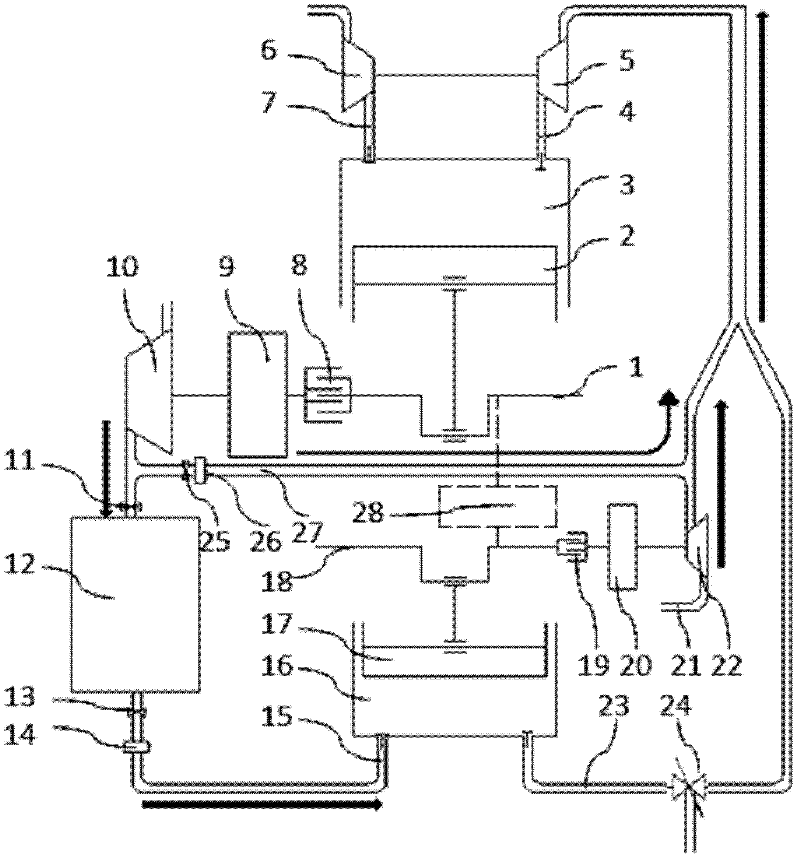
[0018] The structure of the pneumatic internal combustion hybrid engine of the present invention is as figure 1 Shown.
[0019] The pneumatic engine has a pneumatic engine cylinder 16, and the pneumatic engine cylinder 16 is provided with an intake valve, an exhaust valve and a pneumatic engine crankshaft 18. The intake valve is connected to the pressure regulating mechanism B 14, the shut-off valve B 13, and the high pressure gas tank 12 through the intake pipe 15 in sequence. The pneumatic engine crankshaft 18 is connected to the compressor C22 through a clutch B19, a speed regulating mechanism B20. The exhaust valve of the pneumatic engine is connected to the intake pipe 4 of the internal combustion engine through the exhaust pipe 23 of the pneumatic engine. A three-way electromagnetic valve 24 is provided on the exhaust pipe 23 of the pneumatic engine.
[0020] The internal combustion engine has an internal combustion engine cylinder 3, and the internal combustion engine cylinder 3 is provided with at least an intake valve, an exhaust valve and an internal combustion engine crankshaft 1. The intake valve of the internal combustion engine is connected to the intake pipe 4 of the internal combustion engine, and the intake pipe of the internal combustion engine is provided with two inlets, which are respectively connected with the exhaust pipe 23 and the air inlet 21 of the pneumatic engine. A compressor C 22 is provided between the air inlet 21 and the intake pipe of the internal combustion engine.
[0021] The internal combustion engine can also be equipped with an exhaust gas turbocharging system on the internal combustion engine intake pipe 4 and the internal combustion engine exhaust pipe 7, that is, the internal combustion engine intake pipe 4 is equipped with a compressor A5 and the internal combustion engine exhaust pipe 7 is equipped with a turbine 6. The crankshaft 1 of the internal combustion engine is connected to a compressor B 10 through a clutch A 8 and a speed regulating mechanism A 9; the inlet of the compressor B 10 is connected to the atmosphere, and the outlet of the compressor B 10 is connected to a high-pressure gas tank 12. The high-pressure gas tank 12 has at least one high-pressure gas inlet and one high-pressure gas outlet, and a pressure sensor (not shown in the figure) is provided on the high-pressure gas tank. If the exhaust of the pneumatic engine and the boost of the compressor have satisfied the intake of the internal combustion engine, the exhaust gas turbocharging system may not be provided.
[0022] The outlet pipeline of compressor B 10 is equipped with a bypass pipeline 27, and the bypass pipeline 27 is equipped with a stop valve C 25 and a pressure regulating mechanism C 26, which can introduce high pressure gas from the outlet of compressor B 10 to the intake pipe of the internal combustion engine when needed. In the air inlet end.
[0023] The pneumatic engine crankshaft 18 and the internal combustion engine crankshaft 1 can be connected through the crankshaft coupling mechanism 28, so that the pneumatic engine and the internal combustion engine can work in their respective optimal regions, and can work or output power separately. The crankshaft coupling mechanism may be a planetary gear mechanism.
[0024] The operation mode of the pneumatic internal combustion hybrid engine in the present invention is as follows:
[0025] Mode 1:
[0026] The pneumatic machine alone propels the car. At this time, the high-pressure gas tank 12 injects high-pressure gas to the pneumatic engine through the shut-off valve B 13, the pressure regulating mechanism B 14, the pneumatic engine intake pipe 15, and the intake valve, pushing the pneumatic engine piston 17 downward to do work. The valve enters the exhaust pipe 23 of the pneumatic engine. At this time, the three-way solenoid valve 24 on the exhaust pipe 23 of the pneumatic engine is opened, and the exhaust of the pneumatic engine enters the atmosphere directly. At this time, the crankshaft coupling mechanism 28 does not work, and the pneumatic engine crankshaft 18 outputs power alone. In this working condition, the clutch B 19 is in a disengaged state, the pneumatic crankshaft 18 is separated from the compressor C 22, and the compressor C 22 stops working.
[0027] Mode 2:
[0028] The internal combustion engine alone drives the car. At this time, the three-way solenoid valve 24 on the exhaust pipe 23 of the pneumatic engine is opened. The internal combustion engine can be inhaled from the atmosphere through the air inlet 21 and the three-way solenoid valve 24. Boosting effect. At this time, the pressure sensor detects the gas pressure of the high-pressure gas tank 12. If the pressure is lower than the lower limit, the internal combustion engine drives the compressor B 10 through the clutch A 8 and the speed regulating mechanism A 9 to charge the high-pressure gas tank 12; if the pressure is higher than With the upper limit value, the internal combustion engine is separated from the compressor B10. The speed regulating mechanism A 9 can adjust the speed of the compressor B 10 according to the pressure of the high pressure gas tank 12 so that the outlet gas of the compressor B 10 can reach the pressure of the high pressure gas tank 12. During this process, the shut-off valve C 25 on the bypass pipeline 27 is in a closed state to ensure that high-pressure gas can only enter the high-pressure gas tank 12.
[0029] Mode 3:
[0030] Pneumatic engine and internal combustion engine drive the car at the same time. At this time, the high-pressure gas tank 12 injects high-pressure gas to the pneumatic machine through the shut-off valve B 13, the pressure regulating mechanism B 14, and the pneumatic machine intake pipe 15, pushing the pneumatic machine piston 17 downward to do work. After the gas expansion is completed, it enters the pneumatic machine through the exhaust valve. Machine exhaust pipe 23. At this time, the three-way electromagnetic valve 24 on the exhaust pipe 23 of the pneumatic engine is closed, and the exhaust cannot directly enter the atmosphere. The pneumatic engine is separated from the compressor C 22 through the clutch B 19 and the speed regulating device B 20 so that the compressor C 22 does not form a supercharging effect. The gas in the exhaust pipe 23 of the pneumatic engine and the gas in the air inlet 21 are mixed and enter the exhaust gas turbocharging system for supercharging, and then enter the internal combustion engine. At the same time, the pressure sensor detects the gas pressure of the high-pressure gas tank 12. If the pressure is lower than the lower limit, the internal combustion engine drives the compressor B 10 through the clutch A 8, the speed regulating mechanism A 9 to charge the high-pressure gas tank 12; if the pressure is higher than the upper limit Limit, the internal combustion engine is separated from the compressor B10. The speed regulating mechanism A 9 can adjust the speed of the compressor B 10 according to the pressure of the high pressure gas tank 12 so that the outlet gas of the compressor B 10 can reach the pressure of the high pressure gas tank 12. During this process, the shut-off valve C 25 on the bypass line 27 is in a closed state to ensure that the high-pressure gas can only enter the high-pressure gas tank 12.
[0031] Mode 4:
[0032] Pneumatic engine and internal combustion engine drive the car at the same time. At this time, the high-pressure gas tank 12 injects high-pressure gas to the pneumatic machine through the shut-off valve B 13, the pressure regulating mechanism B 14, and the pneumatic machine intake pipe 15, pushing the pneumatic machine piston 17 downward to do work. After the gas expansion is completed, it enters the pneumatic machine through the exhaust valve. Machine exhaust pipe 23. At this time, the three-way electromagnetic valve 24 on the exhaust pipe 23 of the pneumatic engine is closed, and the exhaust cannot directly enter the atmosphere. The pneumatic engine drives the compressor C 22 to work through the clutch B 19 and the speed regulating device B 20. The gas in the exhaust pipe 23 of the pneumatic engine is mixed with the gas from the outlet of the compressor C 22 and then enters the exhaust gas turbocharging system for supercharging, and then enters the internal combustion engine. At the same time, the pressure sensor detects the gas pressure of the high-pressure gas tank 12. If the pressure is lower than the lower limit, the internal combustion engine drives the compressor B 10 through the clutch A 8, the speed regulating mechanism A 9 to charge the high-pressure gas tank 12; if the pressure is higher than the upper limit Limit, the internal combustion engine is separated from the compressor B10. The speed regulating mechanism A 9 can adjust the speed of the compressor B 10 according to the pressure of the high pressure gas tank 12 so that the outlet gas of the compressor B 10 can reach the pressure of the high pressure gas tank 12. During this process, the shut-off valve C 25 on the bypass line 27 is in a closed state to ensure that the high-pressure gas can only enter the high-pressure gas tank 12.
[0033] Mode 5:
[0034] Pneumatic engine and internal combustion engine drive the car at the same time. At this time, the high-pressure gas tank 12 injects high-pressure gas to the pneumatic machine through the shut-off valve B 13, the pressure regulating mechanism B 14, and the pneumatic machine intake pipe 15, pushing the pneumatic machine piston 17 downward to do work. After the gas expansion is completed, it enters the pneumatic machine through the exhaust valve. Machine exhaust pipe 23. At this time, the three-way electromagnetic valve 24 on the exhaust pipe 23 of the pneumatic engine is closed, and the exhaust cannot directly enter the atmosphere. The pneumatic engine is separated from the compressor C 22 through the clutch B 19 and the speed regulating device B 20 so that the compressor C 22 does not form a supercharging effect. At this time, the shut-off valve 25 on the bypass line 27 is opened, and the high-pressure gas at the outlet of the compressor is regulated by the pressure regulating mechanism C 26, and then enters the exhaust gas turbine in the intake pipe 4 of the internal combustion engine together with the exhaust gas from the pneumatic engine exhaust pipe 4. After the pressure system is pressurized, it enters the internal combustion engine. At the same time, the pressure sensor detects the gas pressure of the high-pressure gas tank 12. If the pressure is lower than the lower limit, the internal combustion engine drives the compressor B 10 through the clutch A 8, the speed regulating mechanism A 9 to charge the high-pressure gas tank 12; if the pressure is higher than the upper limit Limit, the internal combustion engine is separated from the compressor B10. The speed regulating mechanism A 9 can adjust the speed of the compressor B 10 according to the pressure of the high pressure gas tank 12 so that the outlet gas of the compressor B 10 can reach the pressure of the high pressure gas tank 12.

PUM

no PUM

Description & Claims & Application Information

We can also present the details of the Description, Claims and Application information to help users get a comprehensive understanding of the technical details of the patent, such as background art, summary of invention, brief description of drawings, description of embodiments, and other original content. On the other hand, users can also determine the specific scope of protection of the technology through the list of claims; as well as understand the changes in the life cycle of the technology with the presentation of the patent timeline. Login to view more.
Why Eureka
Try Eureka