Light engine system for reflective liquid crystal projection display
A liquid crystal projection and reflective technology, applied in the field of light engine systems, can solve the problems of not being able to improve the efficiency of the whole machine, and achieve the effects of increasing system complexity, improving optical efficiency and overall brightness, and maximizing light utilization
- Summary
- Abstract
- Description
- Claims
- Application Information
AI Technical Summary
Problems solved by technology
Method used
Image
Examples
Embodiment 1
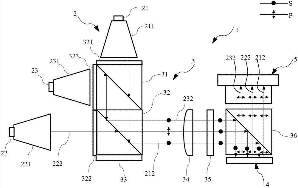
[0035] figure 1 The first embodiment of the present invention for a reflective liquid crystal projection display system 1 is given, including a light source module 2 , a polarized light management module 3 , an image information module 4 and a projection lens 5 .
[0036] The light source module 2 includes a red light LED 21, a green light LED 22, a blue light LED 23, a red light uniform device 211, a green light uniform device 221 and a blue light uniform device 231, and the red LED 21 is connected to the red light uniform device 211. The green LED 22 is connected to the green uniform light device 221 , and the blue LED 23 is connected to the blue light uniform device 231 .
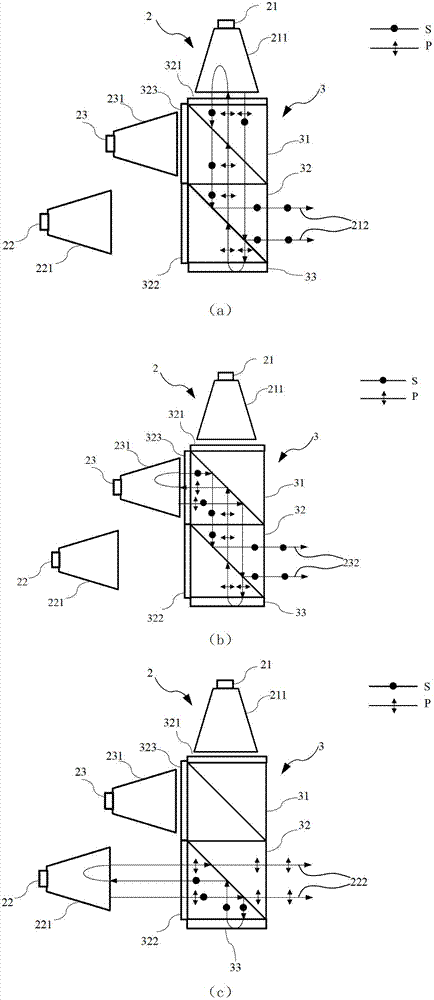
[0037] The natural light of the three primary colors emitted by the red LED 21, the green LED 22, and the blue LED 23 passes through the red light homogenizing device 211, the green light homogenizing device 221 and the blue light homogenizing device 231 respectively, and then collects them into small-an...
Embodiment 2
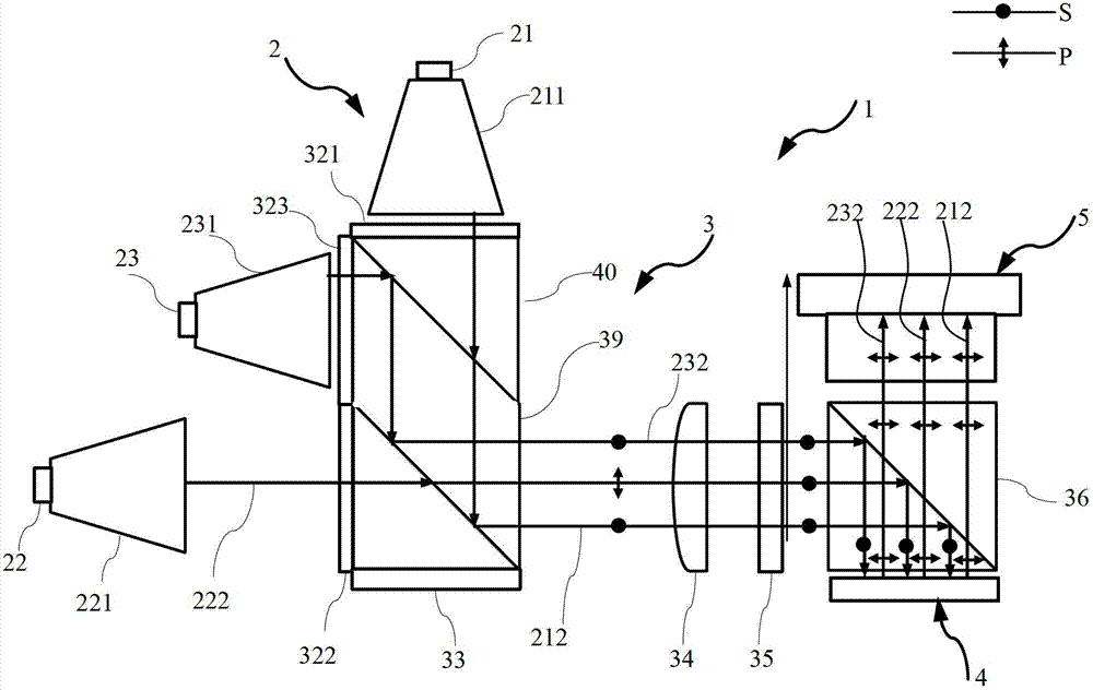
[0050] image 3 A second example of the present invention is given. Compared with the first example, in the polarization color combining unit of the second example, the parallelogram prism 39 is used to glue two first right-angle prisms 40, instead of the dichroic prism 31 and the first PBS, the parallelogram prism A first right-angle prism 40 is glued after being plated with a dichroic film on one color combining surface of the parallelogram prism 39, and a first right-angle prism 40 is glued after being coated with a polarizing beam splitting film on the other color combining surface of the parallelogram prism 39. The advantage is that the interface between the dichroic prism 31 and the first PBS 32 is reduced, which is more conducive to the integration of the optical system.
Embodiment 3
[0052] Figure 4 A third example of the present invention is given. This instance is different from figure 1 The example is that in the polarization color combination unit, the red quarter wave plate 321 and the blue light quarter wave plate 323 are replaced by a wide band quarter wave plate 324, and glued to the dichroic prism 31 and the first PBS, reducing the number of quarter wave plates. exist figure 1 In the example, the design wavelength of each quarter-wave plate adopts the central wavelength of the corresponding light source. Because the spectrum of each primary color itself is very narrow, the common quarter-wave plate can achieve high polarization conversion for monochromatic light, such as Figure 11 (a). In this example, if a traditional quarter-wave plate is used, since the central wavelengths of red light and blue light are far apart, the polarization conversion efficiency of light beyond the design wavelength will decrease rapidly as the wavelength deviate...
PUM
 Abstract
Description
Claims
Application Information
 - R&D
- Intellectual Property
- Life Sciences
- Materials
- Tech Scout
- Unparalleled Data Quality
- Higher Quality Content
- 60% Fewer Hallucinations
Browse by: Latest US Patents, China's latest patents, Technical Efficacy Thesaurus, Application Domain, Technology Topic, Popular Technical Reports.
© 2025 PatSnap. All rights reserved.Legal|Privacy policy|Modern Slavery Act Transparency Statement|Sitemap|About US| Contact US: help@patsnap.com


