Multi-fuel energy-saving furnace

An energy-saving furnace and fuel technology, which is used in solid heating fuels, household furnaces/stoves, lighting and heating equipment, etc., can solve the problems of insufficient combustion of fuel and air, low utilization of heat energy, and insufficient combustion. , to achieve the effect of using smokeless, high combustion value and energy saving

Inactive Publication Date: 2013-10-09
许大明
View PDF3 Cites 0 Cited by
  • Summary
  • Abstract
  • Description
  • Claims
  • Application Information

AI Technical Summary

Problems solved by technology

[0002] At present, the common stoves on the market are in use, and the air naturally flows into the stove, the amount of air entering the stove is very limited, and the mixing ratio of fuel and air cannot reach meet the requirements of full combustion, so most of them still have the problem of insufficient combustion, low combustion value, low heat energy utilization rate, and waste of energy

Method used


Image

  • Multi-fuel energy-saving furnace
  • Multi-fuel energy-saving furnace
  • Multi-fuel energy-saving furnace

Examples


Embodiment 1

[0021] Example 1. Used to burn coal.

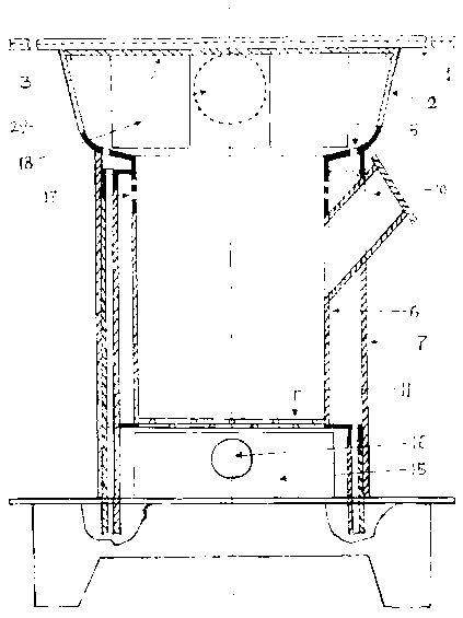
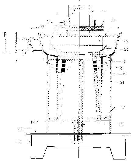
[0022] Such as figure 1 or figure 2 As shown, it includes a furnace panel 1, a furnace pot 2, a furnace cylinder 6, a furnace outer cylinder 7, a third air inlet partition 8, a secondary air inlet pipe 12, a furnace foot bottom plate 13, a third air inlet pipe 14, an ash box 15, Fire baffle ring 18, furnace foot side plate 19, air return ring 20 and furnace core 21, furnace panel 1 is a movable type, is placed on the furnace basin 2 when in use, and is pinned by two latches. There is a furnace ring 3 and a flue gas outlet hole 29 on the furnace basin 2, and a flue gas elbow joint 4 is connected to the flue gas outlet hole 29, and a thermal energy adjustment and heat preservation is installed on the flue gas elbow joint 4. valve 22. There are three air inlet holes 5 in a circle at the bottom of the stove basin 2 . The furnace basin 2 is welded together with the hearth cylinder 6 and the furnace outer cylinder 7 , the furnace ou...

Embodiment 2

[0024] Example 2. It is used to burn firewood, various crop straws and other waste combustibles.

[0025] Such as figure 1 As shown, it includes a furnace panel 1, a furnace basin 2, a furnace cylinder 6, a furnace outer cylinder 7, a third air inlet partition 8, a secondary air inlet pipe 12, a furnace foot bottom plate 13, a third air inlet pipe 14, an ash box 15, Fire baffle ring 18, stove foot side plate 19 and air return ring 20, stove panel 1 are movable, are placed on the stove basin 2 when in use, are pinned by two latches. There is a furnace ring 3 and an exhaust gas outlet hole 29 on the furnace basin 2, and a smoke exhaust gas elbow joint 4 is connected to the smoke exhaust gas outlet hole 29, and a thermal energy adjustment heat preservation device is installed on the exhaust gas elbow joint 4. valve 22. There are three air inlet holes 5 in a circle at the bottom of the stove basin 2 . The furnace basin 2 is welded together with the hearth cylinder 6 and t...


PUM


Abstract

The invention discloses a multi-fuel energy-saving furnace, which comprises a furnace panel (1), a furnace basin (2), a furnace ring (3), a furnace cylinder (6), a furnace outer cylinder (7), and three air inlet partitions ( 8), secondary air inlet pipe (12), furnace foot bottom plate (13), third air inlet pipe (14), ash box (15), fire retaining ring (18), furnace foot side plate (19), return air circle (20), exhaust gas outlet hole (29), tertiary air inlet hole (5), secondary air inlet partition (9), furnace bridge (11), furnace tube secondary air inlet hole (17), primary Air inlet (16), stoker (23), stoker chute (24), stoker insert (25) and furnace cover (26). The invention adopts a fully enclosed structure, forms vaporized combustion through three times of air intake to assist oxygen, greatly improves the combustion value, and has the characteristics of various fuels, high efficiency and energy saving, economical and practical, hygienic and environmentally friendly, and long service life.

Description

technical field [0001] The invention relates to a household stove, in particular to a multi-fuel energy-saving stove. Background technique [0002] At present, when the common stoves on the market are in use, the air naturally flows into the stove, the amount of air entering the stove is very limited, and the mixing ratio of fuel and air cannot meet the requirements of full combustion, so most of them still have insufficient combustion. The problem is that the combustion value is low, the heat energy utilization rate is low, and energy is wasted. Contents of the invention [0003] The technical problem to be solved by the present invention is to provide a multi-fuel energy-saving furnace with high combustion value, high heat energy utilization rate, which can burn various crop stalks for cooking and heating, realizes the recycling and long-term use of ecological resources, and is environmentally friendly and energy-saving, so as to overcome the Insufficiency of existing t...

Claims


Application Information

Patent Timeline
Patent Type & Authority Patents(China)
IPC IPC(8): F24B1/19F24B1/191F24B13/04
CPCY02B40/00
Inventor 许大明
Owner 许大明
Why Eureka
Try Eureka