Electrochemical machining method and device for oil nozzle spray orifice of diesel motor
A diesel engine and processing method technology, applied in electrochemical machining equipment, metal processing equipment, manufacturing tools, etc., can solve the problem of difficulty in controlling the arc shape and arc radius, small arc transition radius in the nozzle hole, and abrasive particles. The problem of high cost of flow processing can achieve the effect of good spray effect, improve the flow coefficient of nozzle holes, and avoid the influence of processing accuracy.
- Summary
- Abstract
- Description
- Claims
- Application Information
AI Technical Summary
Problems solved by technology
Method used
Image

Examples
Embodiment 1
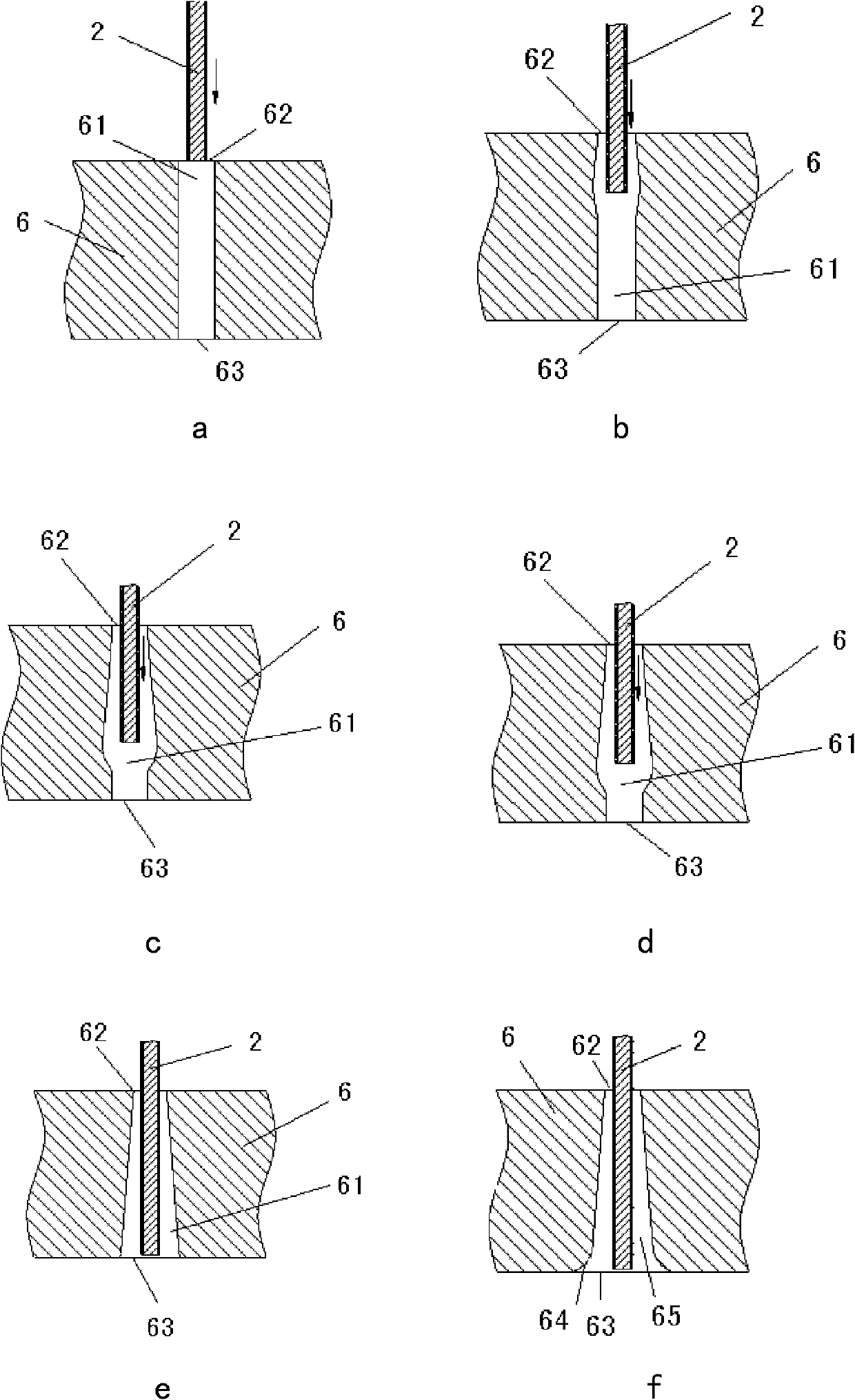
[0030] Such as image 3 As shown in a to 3f, this embodiment includes the following electrolytic machining steps:
[0031] 1) Pre-drilling or EDM a cylindrical or forward conical (that is, the diameter of the outer port is greater than the diameter of the inner port) through hole 61 on the injector workpiece 6;
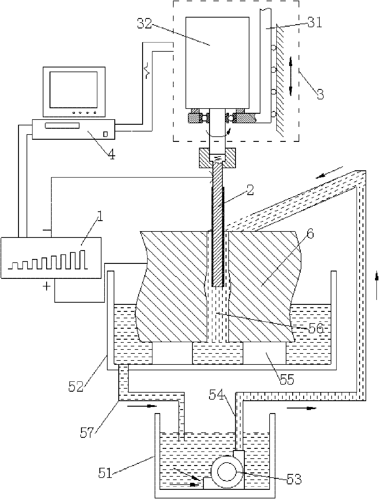
[0032] 2) Fix the fuel injector workpiece 6 on the support frame 55, clamp the tool electrode 2 on the electrode feed mechanism 3, and move the fuel injector workpiece 6 so that the central axis of the through hole 61 on it is aligned with the center axis of the tool electrode 2. The central axes coincide, and the tool electrode 2 is moved so that its end face 23 is located above the outer opening 62 of the through hole 61 on the injector workpiece 6;
[0033] 3) Start the liquid pump 53 to inject the electrolyte 56 into the through hole 61, and the electrolyte 56 flows back from the liquid tank 52 to the electrolyte container 51 to form an electrolyte circulation. T...
Embodiment 2
[0038] The steps of the electrolytic machining method of the present embodiment are basically the same as the steps of the embodiment 1, and the difference between the two is only in the step 4), and the step 4) of the present embodiment is expressed as follows:
[0039] 4) Turn on the electrolytic machining power supply 1. The pulse width and pulse spacing of the electrolytic machining power supply 1 are kept constant during the machining process. The electrode feed mechanism 3 is controlled by the industrial computer 4 to drive the tool electrode 2 into the through hole 61, and from the outside of the through hole 61 The port 62 feeds at a constant speed towards the inner port 63, and the through hole 61 is processed through the electrolyte 56. At the same time, as the tool electrode 2 is gradually fed, the pulse amplitude gradually increases, and the pulse amplitude depends on the required hole shape. The size and size are determined by electrochemical forming rules and proc...
Embodiment 3
[0041] In this embodiment, the reverse conical spray hole 65 of the fuel injection nozzle workpiece 6 that has been processed into a reverse conical shape is polished, and the circular arc transition region 64 is processed, and the electrolytic machining is performed. Step is basically the same as the step of embodiment 1, and the difference between the two is only step 1), step 4) and step 5), and step 1), step 4) and step 5) of the present embodiment are represented as follows:
[0042] 1) Machining an inverted tapered nozzle hole 65 without a circular arc transition zone 64 on the injector workpiece 6 by electric spark method;
[0043] 4) Turn on the electrolytic machining power supply 1, the pulse width, pulse interval, and pulse amplitude of the electrolytic machining power supply 1 remain unchanged during the machining process, and the industrial computer 4 controls the electrode feeding mechanism 3 to drive the tool electrode 2 into the through hole 61, from The outer p...
PUM
 Abstract
Description
Claims
Application Information
 - R&D
- Intellectual Property
- Life Sciences
- Materials
- Tech Scout
- Unparalleled Data Quality
- Higher Quality Content
- 60% Fewer Hallucinations
Browse by: Latest US Patents, China's latest patents, Technical Efficacy Thesaurus, Application Domain, Technology Topic, Popular Technical Reports.
© 2025 PatSnap. All rights reserved.Legal|Privacy policy|Modern Slavery Act Transparency Statement|Sitemap|About US| Contact US: help@patsnap.com