Electromagnetic pump cooling system and control method thereof

A cooling system, electromagnetic pump technology, applied in the direction of pump control, pump components, variable capacity pump components, etc., can solve the problems of limiting the working capacity and safety of electromagnetic pumps, limited cooling capacity, reducing flow resistance, etc., to avoid Electromagnetic pump operation accidents, strong cooling capacity, and the effect of avoiding contact

Inactive Publication Date: 2011-11-16
XI AN JIAOTONG UNIV
View PDF8 Cites 9 Cited by
  • Summary
  • Abstract
  • Description
  • Claims
  • Application Information

AI Technical Summary

Problems solved by technology

Compared with the aforementioned electromagnetic pump, this design reduces the flow resistance, electromagnetic vibration and noise are reduced, and the cooling effect is improved by using forced-flow air cooling, but the electromagnetic pump is still limited due to its limited cooling capacity. Workability and Safety

Method used


Image

  • Electromagnetic pump cooling system and control method thereof
  • Electromagnetic pump cooling system and control method thereof
  • Electromagnetic pump cooling system and control method thereof

Examples


Embodiment 1

[0032] Example 1: Electromagnetic pump operates under low flow conditions

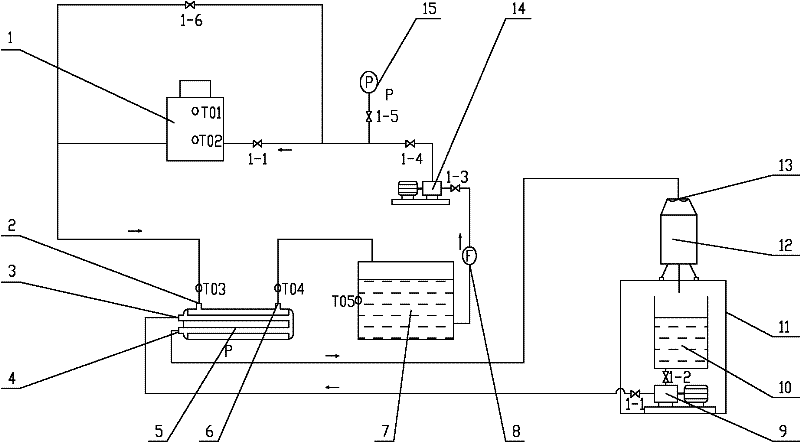
[0033] Such as image 3 , the current liquid metal circuit needs 1m 3 / h flow rate. First, set T0 to 60°C, start the cooling oil pump 14, and satisfy the interlocking conditions for starting the electromagnetic pump. After checking that the flow rate and oil pressure of the oil circuit are normal, the power of the electromagnetic pump can be turned on, and the electromagnetic pump starts to preheat under low voltage. During the preheating period, the oil circuit bypass valve 1-6 should be properly adjusted to reduce the flow through the electromagnetic pump The cooling oil flow of the pump is convenient for preheating.

[0034] When the temperature T01 and T02 of the electromagnetic pump both reach about 150°C, the liquid metal sodium can be charged into the electromagnetic pump, and the electromagnetic pump starts to run officially, and the oil bypass valve 16 is closed at the same time. At this t...

Embodiment 2

[0036] Example 2: Electromagnetic pump operates under medium flow conditions

[0037] Such as image 3 , the current liquid metal circuit needs 5m 3 / h flow rate. First, set T0 to 60°C, start the cooling oil pump 14, and satisfy the interlocking conditions for starting the electromagnetic pump. After checking that the oil flow and oil pressure are normal, turn on the power supply of the electromagnetic pump and adjust its input voltage to about 100V for preheating. At this time, the oil bypass valve 16 remains closed, and all the cooling oil flows through the electromagnetic pump.

[0038] When the temperature T01 and T02 of the electromagnetic pump both reach about 150°C, fill the electromagnetic pump with liquid metal sodium, and the electromagnetic pump starts to run. At this time, adjust the flow rate of the liquid metal to 5m by adjusting the input voltage of the electromagnetic pump 3 / h.

[0039] During operation, in order to provide 5m 3 / h flow rate, the power o...

Embodiment 3

[0040] Example 3: Electromagnetic pump operates under higher flow conditions

[0041] Such as image 3 , the current liquid metal circuit needs 9m 3 / h flow rate. First, set T0 to 60°C, start the cooling oil pump 14, and satisfy the interlocking conditions for starting the electromagnetic pump. After checking that the oil flow and oil pressure are normal, turn on the power supply of the electromagnetic pump and adjust its input voltage to about 100V for preheating. At this time, the oil bypass valve 16 remains closed, and all the cooling oil flows through the electromagnetic pump.

[0042] When the temperature T01 and T02 of the electromagnetic pump both reach about 150°C, fill the electromagnetic pump with liquid metal sodium, and the electromagnetic pump starts to run. At this time, adjust the flow rate of the liquid metal to 9m by adjusting the input voltage of the electromagnetic pump 3 / h.

[0043] To maintain 9m 3 At a flow rate of / h, the electromagnetic pump is ...


PUM


Abstract

The invention discloses an electromagnetic pump cooling system and a control method thereof. The system comprises an electromagnetic pump, an oil-water heat exchanger, an oil tank, a flow meter, a cooling water pump, a cooling water tank, a cooling water tower, a cooling tower fan and a cooling oil pump, wherein the oil-water heat exchanger is connected with the oil tank, the oil tank is connected with the electromagnetic pump through the cooling oil pump, and the electromagnetic pump is connected with the oil-water heat exchanger. The system has the advantages that: the coil of the electromagnetic pump is directly cooled by adopting cooling oil, so the possibility that air and water are in contact with molten metal is avoided; meanwhile, the cooling oil has strong cooling capability, andcan ensure the operating temperature of the coil; control of oil temperature is realized by collocating the cooling tower and using cooling water through the oil-water heat exchanger, so that the cooling capability of the whole system is further ensured; because of a complete monitoring system and a control system, relatively high automation can be realized; and by chain setting of each level, operating accidents of the electromagnetic pump due to error operation of operators are avoided.

Description

technical field [0001] The invention belongs to a cooling system, in particular to an oil-water cooling system during the operation of an electromagnetic pump. Background technique [0002] The electromagnetic pump is driven by electromagnetic force and has no mechanical rotating parts, so it has very good sealing performance and becomes an ideal power device for liquid metal circuits. The basic principle of the electromagnetic pump is to use the electromagnetic coil wound in a certain way to generate a magnetic field when energized, thereby pushing the conductor in it to move in a certain direction. On the one hand, although the electromagnetic pump has no rotating parts, the electromagnetic coil will generate considerable heat when it is energized. If there is no cooling, it is very likely to cause the electromagnetic pump to burn out due to high temperature. On the other hand, the melting point of liquid metal is generally relatively high (for example: liquid metal sodiu...

Claims


Application Information

Patent Timeline
Patent Type & Authority Applications(China)
IPC IPC(8): F04B53/08F04B49/06
Inventor 巫英伟仇子铖田文喜苏光辉李亚秋穗正
Owner XI AN JIAOTONG UNIV
Why Eureka
Try Eureka