Waste heat boiler for power generating system based on tail gas waste heat of pot-type carbon calcining furnace

A waste heat boiler and waste heat power generation technology, applied in the field of waste heat boilers, can solve problems such as high thermal parameters of steam, failure of boilers to meet application requirements, complex composition of imported flue gas, etc., and achieve high heat exchange efficiency, low cost and high promotion value effect

Inactive Publication Date: 2011-11-16
SINOMA ENERGY CONSERVATION
View PDF5 Cites 10 Cited by
  • Summary
  • Abstract
  • Description
  • Claims
  • Application Information

AI Technical Summary

Problems solved by technology

When the flue gas composition is complex and the temperature is high, the traditional waste heat power generation system boiler can no longer be adapted to the power generation system
[0005] The exhaust gas temperature of the tank-type carbon calciner is between 850°C and 1000°C, and the composition of the imported flue gas is complex (including about 7% carbon dioxide, about 8% oxygen, about 74.5% carbon monoxide and about 10.5% water, and contains Sulfur content is 610mg/Nm 3 ), when using the waste heat of the exhaust gas to generate electricity, the thermal parameters of the matching steam are relatively high. In terms of layo

Method used


Image

  • Waste heat boiler for power generating system based on tail gas waste heat of pot-type carbon calcining furnace
  • Waste heat boiler for power generating system based on tail gas waste heat of pot-type carbon calcining furnace

Examples


Embodiment Construction

[0017] The present invention will be further described in detail below in conjunction with the accompanying drawings, so that those skilled in the art can implement it with reference to the description.

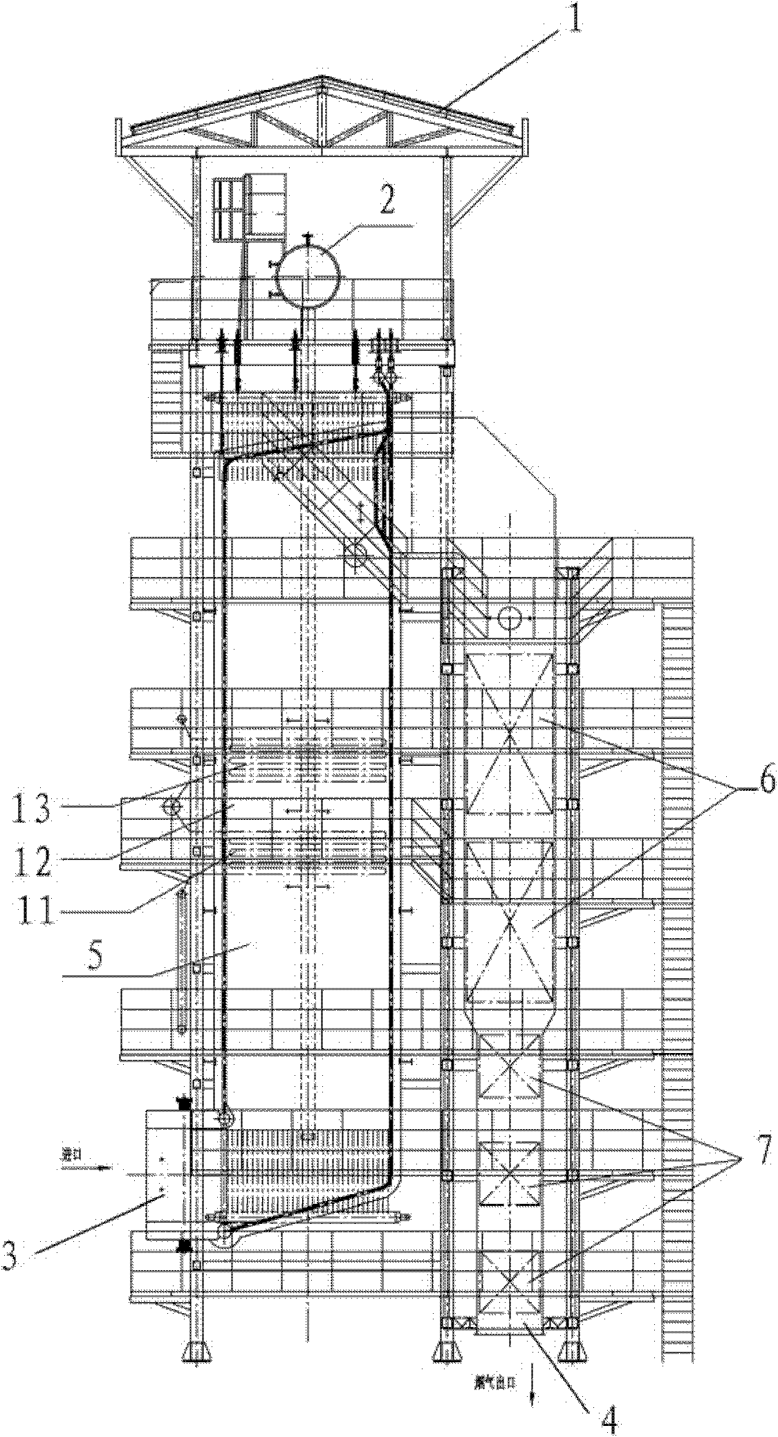
[0018] The present invention starts from the composition and temperature parameters of the flue gas, adopts segmental layout and inverted U-shaped structure for the heat exchange surface of the waste heat boiler, first passes through the radiation cooling chamber for heat exchange, and then the heat exchange device reduces the temperature before entering the evaporator and economizer Conduct convective heat exchange.

[0019] Such as figure 1 As shown, the waste heat boiler used in the waste heat power generation system of the tank-type carbon calciner tail gas according to the present invention has a support frame 1, and the top of the frame 1 is provided with a drum steam drum 2 for steam-water separation, and the frame 1 The bottom is respectively provided with a flue gas...


PUM


Abstract

The invention discloses a waste heat boiler for a power generating system based on tail gas waste heat of a pot-type carbon calcining furnace, and the waste heat boiler is provided with a support frame, wherein the top of the frame is provided with a boiler barrel steam pocket for steamwater separation, and a smoke inlet and a smoke outlet are respectively arranged on the bottom of the frame; a radiation cooling chamber and a heat exchange device are successively arranged between the smoke inlet and the boiler barrel steam pocket, an evaporator and an economizer are successively arranged between the boiler barrel steam pocket and the smoke outlet, and smoke is guided out successively through the smoke inlet, the radiation cooling chamber, the heat exchange device, the evaporator, the economizer and the smoke outlet; and the radiation cooling chamber and the heat exchange device are respectively communicated with the boiler barrel steam pocket. The waste heat boiler for the power generating system based on the tail gas waste heat of the pot-type carbon calcining furnace provided by the invention is designed by fully considering the characteristics of the smoke discharged by the pot-type carbon calcining furnace. The waste heat boiler provided by the invention has the advantages of not only high heat exchange efficiency, but also lower manufacturing cost and higher popularization value.

Description

technical field [0001] The invention relates to a waste heat boiler, in particular to a waste heat boiler used in a tank type carbon calciner tail gas waste heat power generation system. Background technique [0002] At present, the pure low-temperature waste heat power generation technology is mainly used in the cement industry. The characteristics of the flue gas composition determine that when designing the heat exchange surface of the waste heat boiler at the kiln head, there is no need to consider too much the influence of acid dew point corrosion on the material of the waste heat boiler in the low temperature section. [0003] Most of the waste heat boilers in the field of pure low-temperature waste heat power generation are medium and low-temperature heat exchangers. Because the heat transfer temperature is not high, the internal heat transfer structure of the boiler is relatively simple, that is, most of them adopt the methods of top inlet and bottom outlet, top inlet...

Claims


Application Information

Patent Timeline
IPC IPC(8): F22B1/18F22B31/08
Inventor 魏连有张福滨陶军普
Owner SINOMA ENERGY CONSERVATION
Why Eureka
Try Eureka