
Application-specific integrated circuit for remote infrared photoelectric switch and remote infrared photoelectric switch using same

An integrated circuit, photoelectric switch technology

Inactive Publication Date: 2011-11-16
SHANGHAI LINGXIN MICROELECTRONICS
View PDF0 Cites 7 Cited by
  • Summary
  • Abstract
  • Description
  • Claims
  • Application Information

AI Technical Summary

Problems solved by technology

[0006] 1. The circuit parameters are greatly affected by the discreteness of external passive components, and the product consistency is poor
[0007] 2. Using analog signal processing method, poor anti-interference ability
[0008] 3. The detection sensitivity is low. When it is necessary to make a long-distance and ultra-long-distance photoelectric switch, a very high receiving sensitivity is required, and a simple analog amplifier circuit can easily cause self-excitation when it amplifies the received signal by a very high multiple. Oscillation and failure
[0009] 4. The accuracy is poor. Usually, diodes, triodes or simple gate circuits are used as detection devices. The detection ability of weak signals is extremely limited, which limits the improvement of detection sensitivity.
[0010] 5. In order to increase the receiving distance, we can only increase the transmitting power of the transmitting end. On the one hand, the power consumption is increased, and on the other hand, the transmitting device works in a high current environment for a long time, which accelerates the aging process of the device and shortens the product life.
However, the system gain cannot be increased indefinitely. One of the most important reasons is that if the gain of the amplifier is too large, it is easy to cause self-excited oscillation, resulting in abnormal operation of the receiver.
Generally, the gain of the amplifier should not exceed 60dB
[0013] In general photoelectric switch products, some frequency parameters, time constants, detection thresholds, etc. are set through peripheral passive components such as resistors and capacitors. Due to the discreteness of resistors and capacitors and the influence of temperature characteristics, the product Consistency, stability is negatively affected

Method used


Image

  • Application-specific integrated circuit for remote infrared photoelectric switch and remote infrared photoelectric switch using same
  • Application-specific integrated circuit for remote infrared photoelectric switch and remote infrared photoelectric switch using same
  • Application-specific integrated circuit for remote infrared photoelectric switch and remote infrared photoelectric switch using same

Examples


specific Embodiment approach

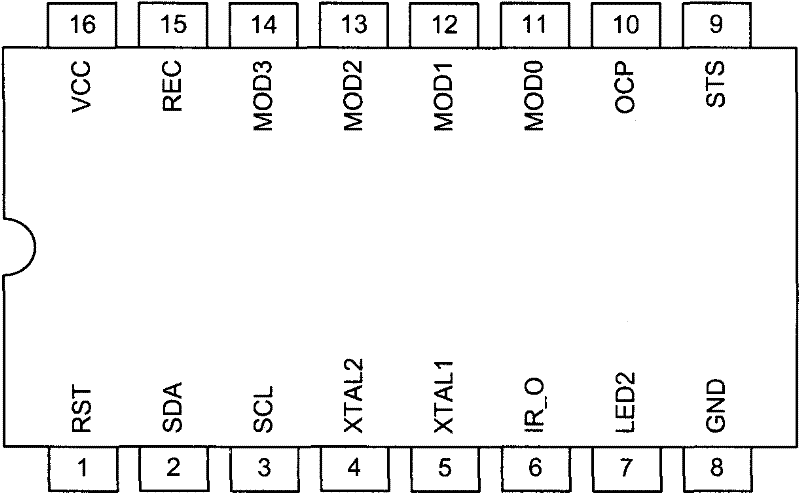
[0085] First kind of implementation mode, the basic application schematic diagram ( Figure 4 ). Figure 4 Describes how to use the ASIC, infrared emitting diode, infrared receiving phototransistor and simple peripheral devices to form a complete photoelectric switch. exist Figure 4 Among them, when driving the infrared light-emitting diode, only the internal drive of the application-specific integrated circuit is used, and the driving capability is limited; the photoelectric signal received by the infrared phototransistor directly enters the application-specific integrated circuit without external amplification, so the receiving sensitivity is also limited; It is suitable for manufacturing photoelectric switches within a detection distance of 15 meters.

[0086] The second kind of implementation mode, describes the long-distance through-beam type photoelectric switch emitting probe schematic diagram ( Figure 5 ). In this application mode, only the emission function of t...


PUM


Abstract

The invention relates to an application-specific integrated circuit for a remote infrared photoelectric switch and the remote infrared photoelectric switch using the same. The application-specific integrated circuit has an internal high speed analogue-to-digital converter (ADC) and a digital signal processing function. At least the 8bit ADC, a digital matched filter (DMF) adopting a finite impulse response (FIR) way, a digital bandpath filter (DBPF) adopting an infinite impulse response (IIR) way, a carrier detector and a digital monostable unit are arranged in the application-specific integrated circuit.

Description

technical field [0001] The invention relates to a dedicated integrated circuit for a long-distance infrared photoelectric switch and a photoelectric switch using the integrated circuit. Background technique [0002] The photoelectric switch is a member of the large family of sensors. It uses infrared light-emitting diodes as sending components, photosensitive devices such as photoresistors, photocells, photodiodes or phototransistors as receiving components, and infrared light sources as media to control the on-off of circuits. Light is an electromagnetic ray, its characteristics are like radio waves and X-rays, and its transmission speed is about 300,000 km / s, so it can be received at the moment of emission. The infrared photoelectric switch uses near-infrared rays and infrared rays (wavelength 850nm-940nm) invisible to human eyes to detect the blocking or reflection of the light beam by the object, and the circuit is gated by the synchronous loop to detect the presence or ...

Claims


Application Information

Patent Timeline
Patent Type & Authority Applications(China)
IPC IPC(8): H03K17/78
Inventor 汪运来王振宇陈宇
Owner SHANGHAI LINGXIN MICROELECTRONICS
Learn More