Method for measuring incident angle of laser by multi-beam laser heterodyne quadratic harmonic method

A laser heterodyne and second harmonic technology, which is applied in the measurement angle, measurement device, surveying and navigation, etc., can solve the problems of low measurement accuracy, slow signal processing operation speed, and poor laser difference frequency signal collection effect.

Inactive Publication Date: 2013-09-04
HARBIN INST OF TECH
View PDF0 Cites 0 Cited by
  • Summary
  • Abstract
  • Description
  • Claims
  • Application Information

AI Technical Summary

Problems solved by technology

[0004] The present invention aims to solve the problem of low measurement accuracy caused by the poor acquisition effect of laser difference frequency signals and slow operation speed of signal processing in the existing multi-beam laser heterodyne method for measuring laser incident angles, thereby providing a multi-beam laser heterodyne Method of Measuring Laser Incident Angle by Difference Second Harmonic Method

Method used


Image

  • Method for measuring incident angle of laser by multi-beam laser heterodyne quadratic harmonic method
  • Method for measuring incident angle of laser by multi-beam laser heterodyne quadratic harmonic method
  • Method for measuring incident angle of laser by multi-beam laser heterodyne quadratic harmonic method

Examples


specific Embodiment approach 1

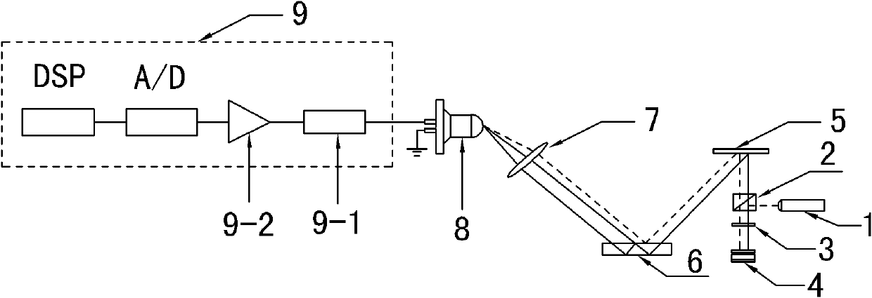
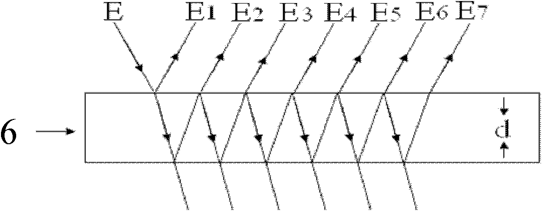
[0061] Specific implementation mode 1. Combination figure 1 Illustrate this specific embodiment, the device that multi-beam laser heterodyne second harmonic method measures laser incident angle, it comprises H 0 Solid-state laser 1, polarizing beam splitter PBS2, quarter-wave plate 3, vibrating mirror 4, plane mirror 5, glass plate of known thickness 6, converging lens 7, photodetector 8 and signal processing system 9,

[0062] h 0 The linearly polarized light emitted by the solid-state laser 1 is incident on the quarter-wave plate 3 after being reflected by the polarizing beam splitter PBS2, and the light beam transmitted by the quarter-wave plate 3 is incident on the light-receiving surface of the vibrating mirror 4, The light beam reflected by the galvanometer 4 is transmitted to the polarizing beam splitter PBS2 after being transmitted by the quarter-wave plate 3 again, and the light beam transmitted by the polarizing beam splitting mirror PBS2 is incident on the reflecti...

specific Embodiment approach 2

[0065] Embodiment 2. The difference between this embodiment and the multi-beam laser heterodyne second harmonic method for measuring the laser incident angle described in Embodiment 1 is that the signal processing system 9 is composed of a filter 9-1, A preamplifier 9-2, an analog-to-digital converter A / D and a digital signal processor DSP are composed, and the filter 9-1 filters the received electrical signal output by the photodetector 8 and then sends it to the preamplifier 9 -2, the signal amplified by the preamplifier 9-2 is output to the analog-to-digital converter A / D, and the analog-to-digital converter A / D sends the converted digital signal to the digital signal processor DSP.

specific Embodiment approach 3

[0066] Specific Embodiment Three. The difference between the multi-beam laser heterodyne second harmonic method for measuring the laser incident angle described in the first or second specific embodiment is that the vibrating mirror 4 is a Doppler vibrating mirror. The vibration equation of the Puller galvanometer is:

[0067] x ( t ) = at 2 2 - - - ( 1 )

[0068] The velocity equation of the Doppler galvanometer is:

[0069] v(t)=at (2)

[0070] where a is the vibration acceleration, c is the speed of light, and t is time.


PUM


Abstract

The invention discloses a method for measuring the incident angle of laser by a multi-beam laser heterodyne quadratic harmonic method, relating to a device and method for measuring an incident angle of laser, and solving the problem of relative low measurement precision due to poor laser difference frequency signal quality and low signal treatment computing speed when a multi-beam laser heterodyne method is adopted for measuring the incident angle of laser at present. In the invention, a vibration mirror is added on an optical path, and the vibration mirror does uniformly accelerated motion to carry out frequency modulation on light incoming to the front surface of the vibration mirror at different moments, and angle information to be tested is loaded to frequency difference of quadratic harmonics of heterodyne signals, thereby further obtaining the incident angle information of the laser. The invention is suitable for measuring the incident angle of laser.

Description

technical field [0001] The invention relates to a method for measuring the incident angle of laser light. Background technique [0002] Precision angle measurement is a problem that has been faced and urgently needed to be solved in the field of engineering. With the development of science and technology, angle measurement equipment and measurement methods are constantly being introduced, such as code discs, permanent magnet synchronous motors, laser scanners, inductive synchros, space Fourier spectrometers and four-quadrant detectors, etc. Angle-measuring devices and angle-measuring equipment developed using these devices have been widely used. Angle measurement methods include CCD optical angle measurement method, PIP interferometry method, imaging grating self-collimation angle measurement method, self-collimation angle measurement method based on Moiré fringes, etc. These methods generally cannot meet the requirements of high-accuracy angle measurement. Since optical ...

Claims


Application Information

Patent Timeline
Patent Type & Authority Patents(China)
IPC IPC(8): G01C1/00
Inventor 李彦超王春晖高龙曲杨张峰
Owner HARBIN INST OF TECH
Why Eureka
Try Eureka