
Online detecting method and device for air leakage quantity of vacuum system of turbo generator unit

A technology for turbogenerator sets and vacuum systems, applied in measuring devices, using liquid/vacuum degree for liquid tightness measurement, measuring capacity, etc., can solve the problems of unfavorable unit safety, increase air solubility, vacuum drop, etc., and achieve measurement Simple mechanism, clear measurement principle and convenient installation

Inactive Publication Date: 2011-11-23
SHANDONG ELECTRIC POWER RES INST +1
View PDF4 Cites 34 Cited by
  • Summary
  • Abstract
  • Description
  • Claims
  • Application Information

AI Technical Summary

Problems solved by technology

[0004] 1. The air leaking into the condenser, in addition to increasing the pressure and temperature of the exhaust steam and reducing the economy of the steam turbine, will also deform the low-pressure cylinder of the steam turbine due to high steam temperature, causing the unit to vibrate
[0005] 2. Due to the increase of partial pressure of air, the solubility of air in water is increased, the corrosion of low-pressure pipes and low-pressure heaters is aggravated, and the burden of deaerator is increased, which is not good for the safety of the unit
[0006] 3. Air accumulates around the water pipe, which increases the heat transfer resistance, increases the heat transfer end difference, and reduces the vacuum; the increase in air partial pressure also increases the supercooling of condensed water and increases the burden on the air extractor, etc.
[0012] It can be seen that this method requires multiple measurements, and artificially put air into the condenser, which greatly damages the vacuum and is not conducive to safe production.

Method used


Image

  • Online detecting method and device for air leakage quantity of vacuum system of turbo generator unit
  • Online detecting method and device for air leakage quantity of vacuum system of turbo generator unit
  • Online detecting method and device for air leakage quantity of vacuum system of turbo generator unit

Examples


example

[0067] Parameters obtained by online measurement: temperature t 2 : 35°C, pressure p 2 : 106kpa, relative humidity: 50%, gas velocity: 1.5m / s, the pipe diameter of the exhaust pipe is 0.05m, and the cross-sectional area S=3.14×0.05 2 =0.0079m 2 ,

[0068] From formula (6) get V 空气 =V 湿空气 =v×S=1.5m / s×0.0079m 2 =0.0119m 3 / s,

[0069] From the saturated steam chart, the saturated steam pressure p at 35°C s It is: 5.626kpa. Substitute the above measured and calculated parameters into formula (5):

[0070] G 空气 =29×(106kpa-50%×5.626kpa)×0.0119m 3 / s÷[8.314J / (mol·K)×(35+273.15)]=0.0139kg / s=0.0139×3600kg / h=50.0378kg / h

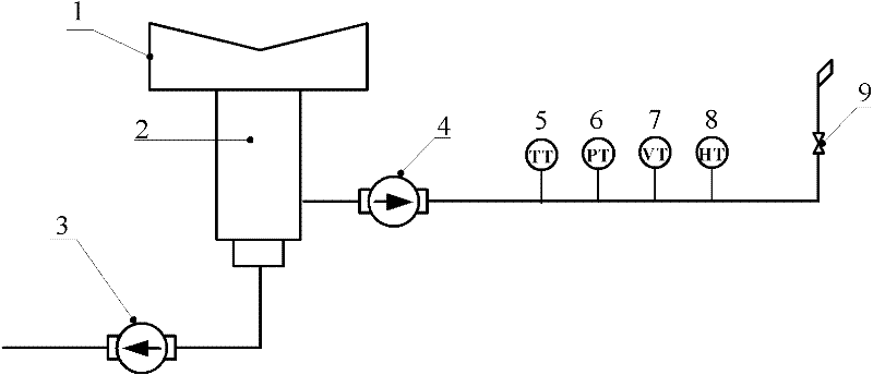
[0071] figure 2 Shown is an on-line detection device for air leakage of a vacuum system of a turbogenerator set provided by the present invention, which is connected to a water ring vacuum pump 4 on the air pumping pipeline of the condenser 2, and the pipeline behind the water ring vacuum pump is sequentially A temperature sensor 5, a pressure sensor 6,...


PUM


Abstract

The invention relates to an online detecting method and device for air leakage quantity of a vacuum system of a turbo generator unit. The device and method can be used for measuring the amount of the air leaked from a condenser which is vacuumized by using a water-ring vacuum pump, on line. The method comprises the following specific steps of: additionally arranging a temperature sensor, a pressure sensor, a gas flow rate sensor and an absolute humidity sensor behind the water-ring vacuum pump, determining the mass flow of the water vapor in a pump-out pipeline in certain particular working condition through parameters measured by the sensors, and calculating to obtain the mass flow of the pumped-out air by using a thermodynamic formula, wherein the mass flow of the pumped-out air is the sum of air leak-in rates of all negative pressure parts of the whole vacuum system. The invention has the advantages of clear and accurate measuring principle, simple measuring mechanism, convenience for installation and capabilities of measuring air leakage amount of the condenser on line and providing a reliable parameter basis for the vacuum system of the turbo generator unit to maintain a higher vacuum level and a guarantee for the safe and economic production of a power plant.

Description

technical field [0001] The invention relates to an on-line detection method and device for the air leakage of the vacuum system of a steam turbine generator set in a power plant. Background technique [0002] The vacuum system of the turbogenerator unit includes: the steam side of the condenser, the air extraction system and other negative pressure parts. Its function is to enable the steam to convert the enthalpy into the kinetic energy of the steam turbine to the maximum extent, and finally convert it into electrical energy. The vacuum of the condenser has a great influence on the economic benefits of the unit. Every 1kPa increase in the vacuum value of the condenser will reduce the coal consumption of power supply by about 3g / kW·h. Therefore, maintaining a high vacuum of the turbo-generator unit can significantly improve the economy of the power plant. [0003] In addition, from the perspective of safe production, it is also essential to maintain the vacuum of the turboge...

Claims


Application Information

Patent Timeline
IPC IPC(8): G01M3/26G01F15/07
Inventor 王学同郭盈
Owner SHANDONG ELECTRIC POWER RES INST
Learn More